Manufacture of a hollow aerofoil

Inactive Publication Date: 2016-09-15
ROLLS ROYCE PLC
View PDF2 Cites 4 Cited by
  • Summary
  • Abstract
  • Description
  • Claims
  • Application Information

AI Technical Summary

Benefits of technology

[0014]It is therefore desirable to manufacture hollow aerofoil components by using a plate to cover a pocket (so as to take advant

Problems solved by technology

Such processes may generate aerofoils with some advantageous properties, such as thin skin thickness and tight dimensional tolerance, but they involve significant material wastage.
This material wastage makes these processes expensive, due at least to high material cost for a given size of hollow aerofoil component.
However, the dimensional tolerances are not so accurate.
This may be because distortion is introduced in the process of attaching the plate to the pocketed aerofoil.
Additionally, tolerance errors may “stack-up” in the process used to produce the pocketed aerofoil, the process used to produce the plate, and the process/feature used to locate the plate into position in the pocket, w

Method used


Image

  • Manufacture of a hollow aerofoil
  • Manufacture of a hollow aerofoil
  • Manufacture of a hollow aerofoil

Examples


Embodiment Construction

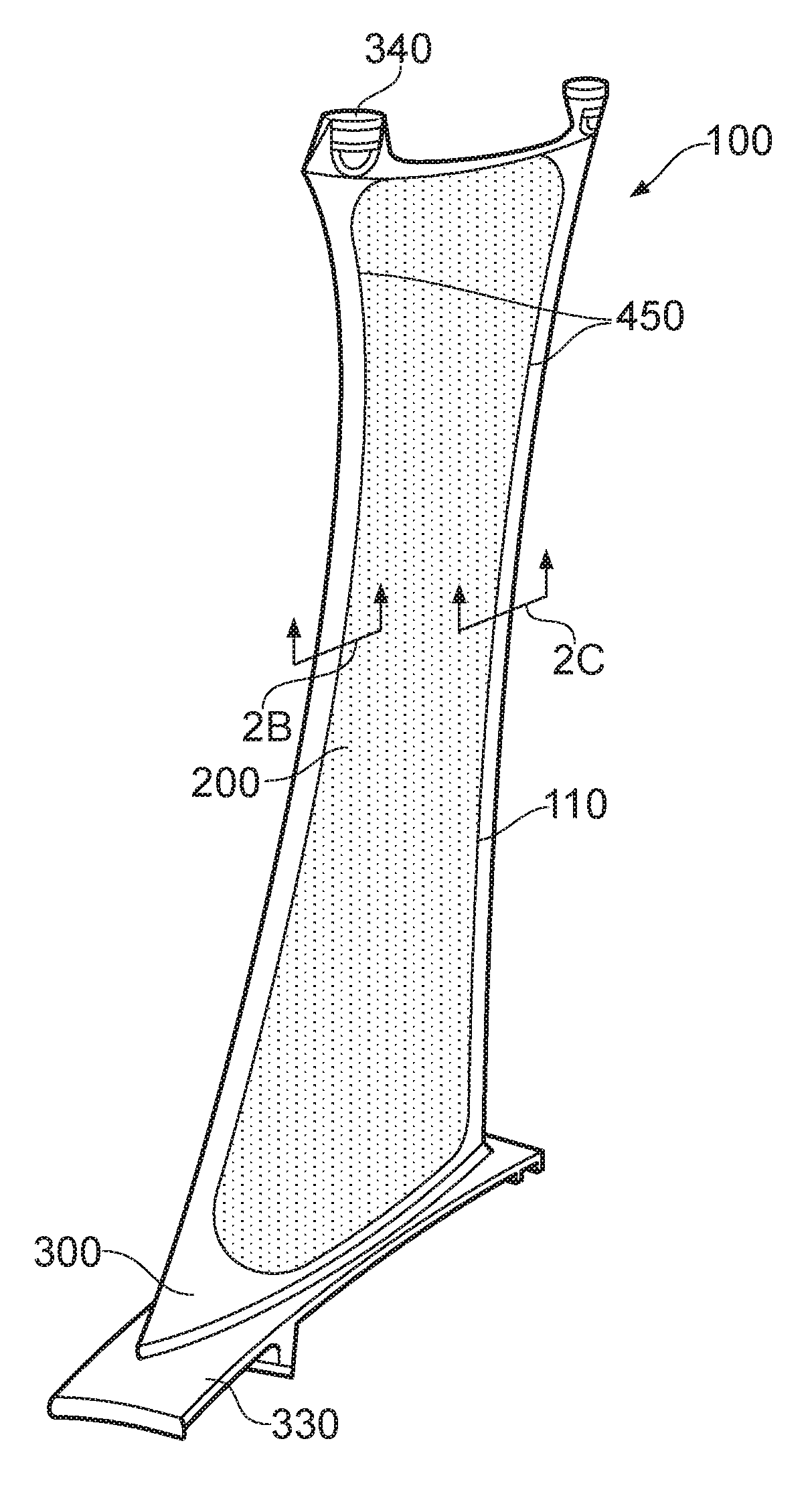
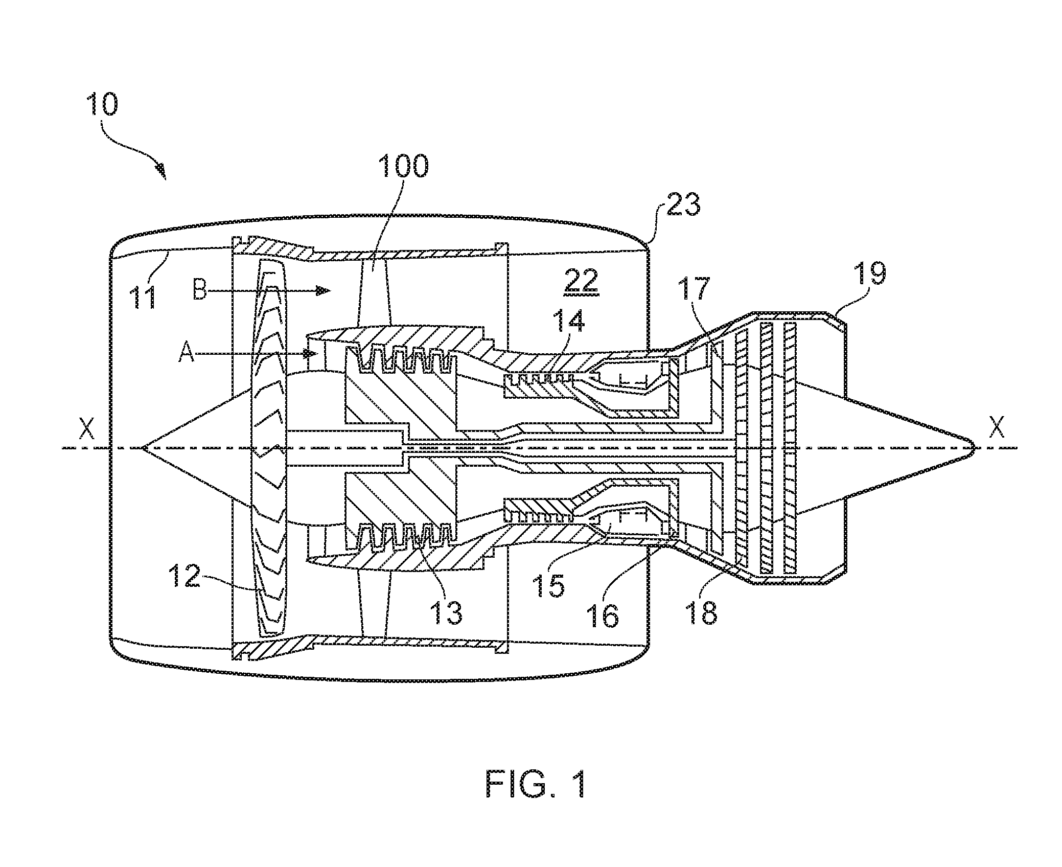
[0051]With reference to FIG. 1, a ducted fan gas turbine engine generally indicated at 10 has a principal and rotational axis X-X. The direction X-X may be referred to as the axial direction of the engine. The engine 10 comprises, in axial flow series, an air intake 11, a propulsive fan 12, an intermediate pressure compressor 13, a high-pressure compressor 14, combustion equipment 15, a high-pressure turbine 16, an intermediate pressure turbine 17, a low-pressure turbine 18 and a core engine exhaust nozzle 19. A nacelle generally surrounds the engine 10 and defines the intake 11, a bypass duct 22 and a bypass exhaust nozzle 23.

[0052]The gas turbine engine 10 works in a conventional manner so that air entering the intake 11 is accelerated by the fan 12 to produce two air flows: a first air flow A into the intermediate pressure compressor 13 and a second air flow B (which may be referred to as a bypass flow B) which passes through the bypass duct 22 to provide propulsive thrust. The i...


PUM

PropertyMeasurementUnit
Thicknessaaaaaaaaaa
Shapeaaaaaaaaaa
Distanceaaaaaaaaaa

Abstract

A method of manufacturing a hollow aerofoil component for a gas turbine engine comprises using a capping panel to cover a pocket in a pocketed aerofoil body. The pocketed aerofoil body has a ledge of substantially constant thickness that extends around its perimeter, and to which the capping panel is joined (e.g. welded) during manufacture. This ensures that the geometry of the join is consistent around the perimeter, meaning that the resulting join has improved properties, for example in terms of residual stress and/or distortion.

Description

CROSS-REFERENCE TO RELATED APPLICATIONS[0001]This application is based upon and claims the benefit of priority from British Patent Application Number GB1504276.5 filed 13 Mar. 2015, the entire contents of which are incorporated by reference.BACKGROUND[0002]1. Field of the Disclosure[0003]The present disclosure relates to a hollow aerofoil.[0004]2. Description of the Related Art[0005]Aerofoil shaped components are used throughout gas turbine engines. For example, aerofoil shaped stator vanes and rotor blades are used to guide gas through the engine, for example both in the turbine and the compressor, including the fan and associated guide vanes.[0006]Weight reduction is an important consideration in gas turbine engines, particularly, although not exclusively, for gas turbine engines used to power aircraft. Generally, the lower the weight of the component the better the performance of the aircraft to which it is fitted, for example in terms of fuel consumption. To this end, it is know...

Claims


Application Information

Patent Timeline
IPC IPC(8): F01D5/18F01D9/04
CPCF01D5/18F01D9/041F05D2230/233F05D2230/10F05D2230/234F05D2220/32B23P15/04F01D5/147F04D29/324F05D2230/232F04D29/023F04D29/542F01D5/14F01D5/141Y02T50/60
Inventor CROWSTON, IAN
Owner ROLLS ROYCE PLC
Why Eureka
Try Eureka