Compact stacked fin heat exchanger

a heat exchanger and stacked fin technology, applied in the direction of lighting and heating apparatus, heating types, laminated elements, etc., can solve the problems of increasing product cost and high pressure loss, and achieve the effect of high manufacturing process efficiency

Inactive Publication Date: 2016-09-15
J R THERMAL
View PDF4 Cites 5 Cited by
  • Summary
  • Abstract
  • Description
  • Claims
  • Application Information

AI Technical Summary

Benefits of technology

[0004]The present invention enables tight fin pitches, down to approximately 1.0 mm, for air to air heat exchangers, with air streams separated by metal foil. These fin pitches can enable twice the fin density and twice the heat transfer coef

Problems solved by technology

While this method is used quite frequently, the formation of the rolled edge 104 is a time consuming process, since the edge can't be formed with a simple up/down progressive

Method used


Image

  • Compact stacked fin heat exchanger
  • Compact stacked fin heat exchanger
  • Compact stacked fin heat exchanger

Examples


Embodiment Construction

[0020]The present invention is directed to a compact stacked fin heat exchanger. The configuration and use of the presently preferred embodiments are discussed in detail below. It should be appreciated, however, that the present invention provides many applicable inventive concepts that can be embodied in a wide variety of contexts other than a stacked fin heat exchanger. Accordingly, the specific embodiments discussed are merely illustrative of specific ways to make and use the invention, and do not limit the scope of the invention.

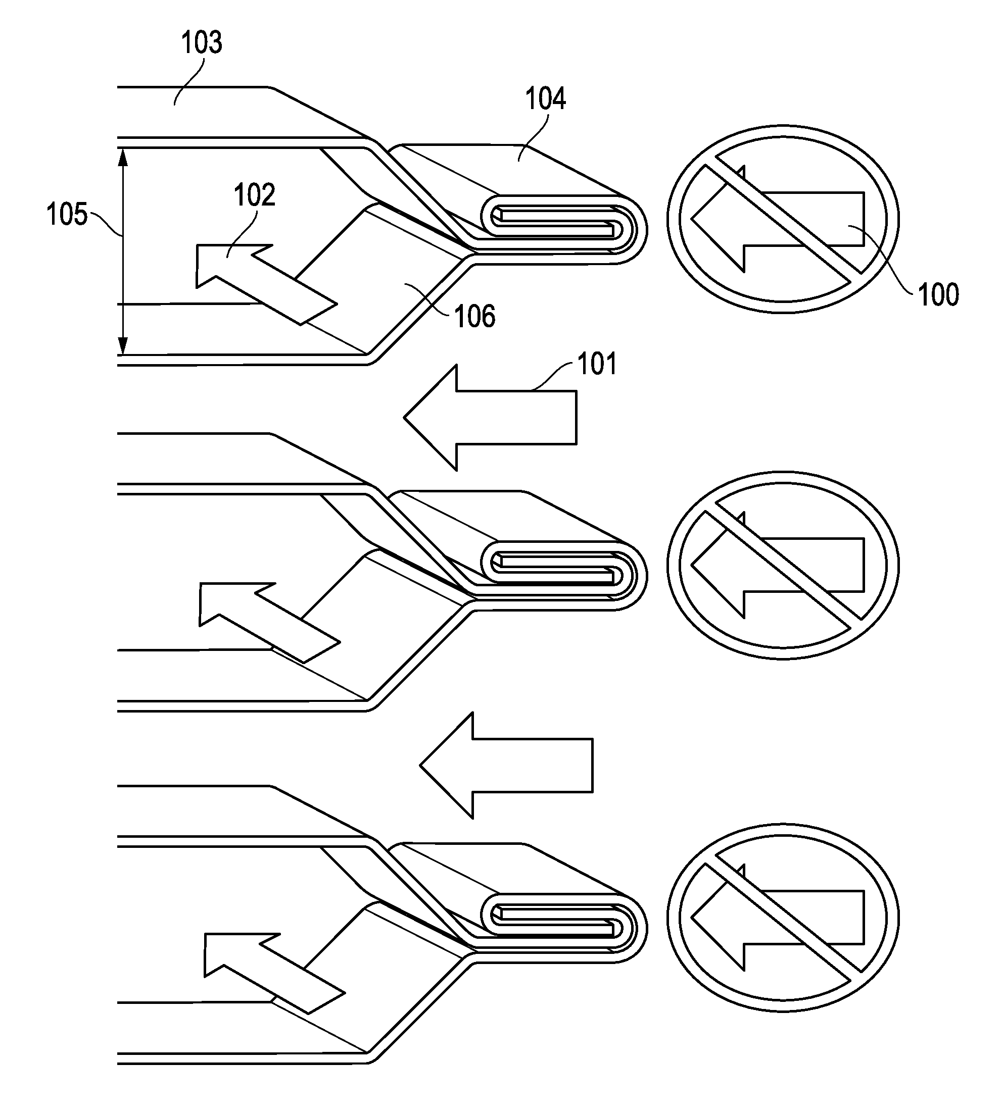
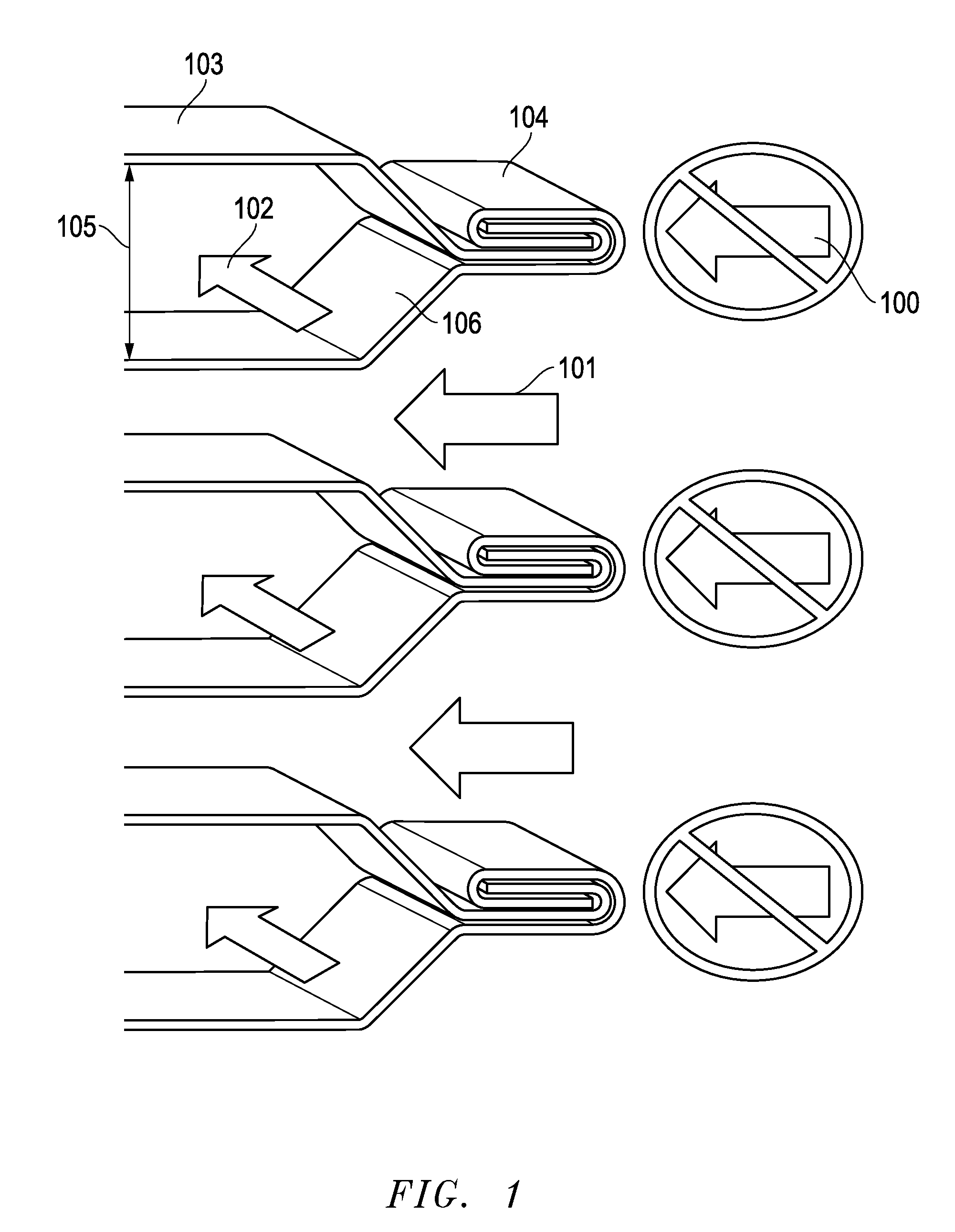
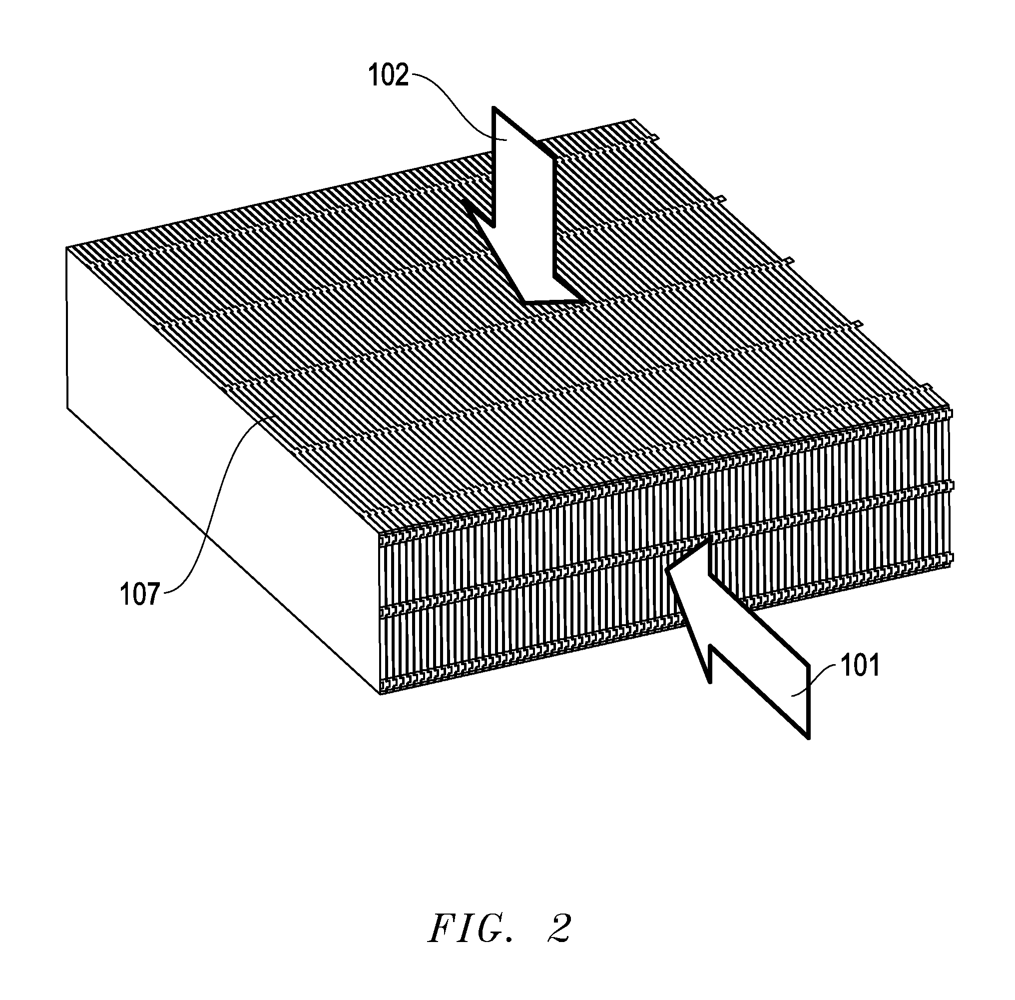
[0021]A representation of one embodiment of the present invention is presented in FIG. 2. Two separate airstreams enter the heat exchanger 107 and transfer heat without mixing. A first airstream 101 has a relatively high temperature when entering the heat exchanger 107, and releases heat to a second airstream 102 that has a relatively low temperature when entering the heat exchanger 107. As the first airstream 101 releases heat, its temperature reduces, ...


PUM


Abstract

A method and system is disclosed in which an air to air heat exchanger keeps two air streams separate through the use of metal fins. Edges of alternating fins are folded so that the end is in the proximity of the adjacent fin and the remaining gap is sealed. The fin stack is held together by interlocking features or through the use of a tube, in which case the fin stacks may be stamped and stacked on alignment stakes during production using the same holes as the tubes. The heat exchanger may have extended use in removing moisture and heat from a hot humid air stream. The heat exchanger has utility in heat recovery ventilation systems, clothes dryer heat recovery or other air to air heat exchanger processes where the pressure difference between the airstreams is less than approximately 5000 Pa.

Description

PRIORITY STATEMENT UNDER 35 U.S.C. §119 & 37 C.F.R. §1.78[0001]This non-provisional application claims priority based upon prior U.S. Provisional Patent Application Ser. No. 62 / 130,063 filed Mar. 9, 2015 in the name of Jeremy Rice entitled “Compact Stacked Fin Heat Exchanger,” the disclosure of which is incorporated herein in its entirety by reference as if fully set forth herein.BACKGROUND OF THE INVENTION[0002]Air to air heat exchangers are used in many heat transfer and heat recovery applications. In applications where heat is desired to be transferred between two separated airstreams without the transfer of moisture, metal foil, often aluminum, is used as the boundary to prevent mixing between the two airstreams. As depicted in FIG. 1, at the edge of the fins 103, it is necessary to block airflow 100 from entering the gap between one pair of fins 103, while allowing the same stream of airflow 101 to enter the neighboring gap. This alternating pattern of allowing airflow to enter...

Claims


Application Information

Patent Timeline
IPC IPC(8): F28F9/007F28F3/10B21D53/06F28D9/00
CPCF28F9/0075B21D53/06F28F3/10F28D9/0037F28F2275/02F24F12/006F28D9/0062F28F2230/00F28F2275/14Y02B30/56
Inventor RICE, JEREMY
Owner J R THERMAL
Why Eureka
Try Eureka