
High brightness polarizing plate and liquid crystal display device including the same

Active Publication Date: 2016-09-15
LG CHEM LTD
View PDF8 Cites 3 Cited by
  • Summary
  • Abstract
  • Description
  • Claims
  • Application Information

AI Technical Summary

Benefits of technology

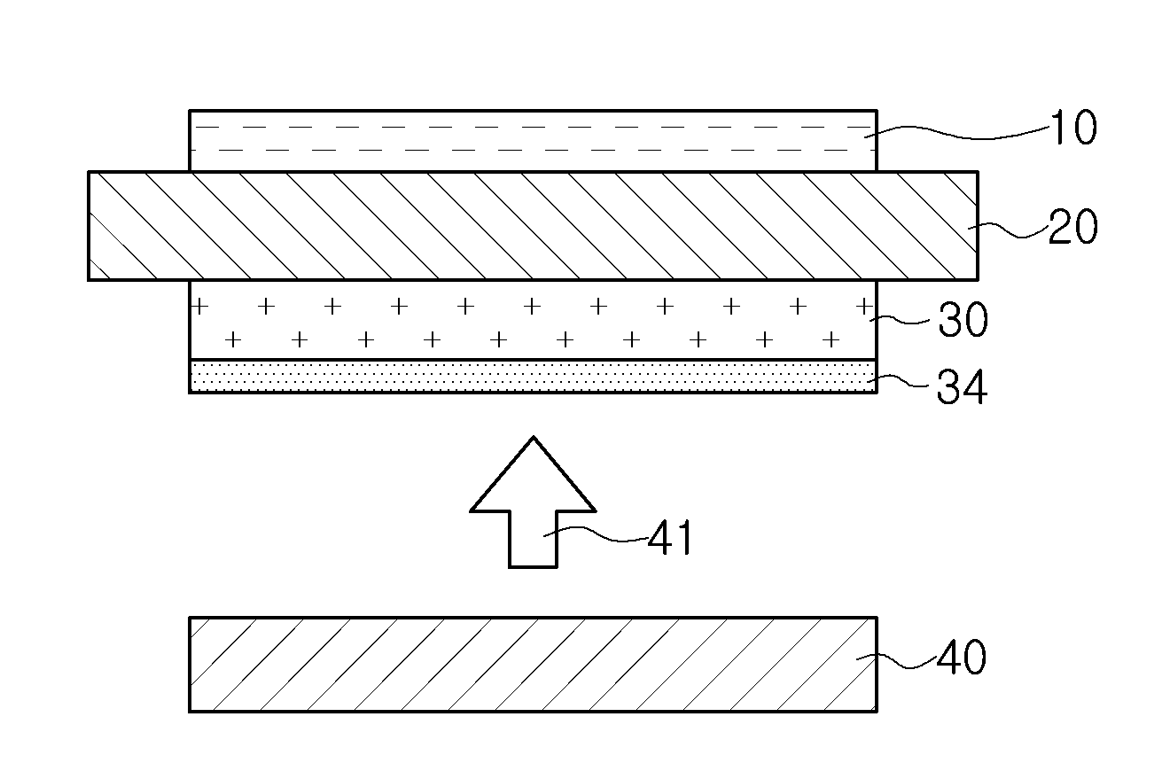
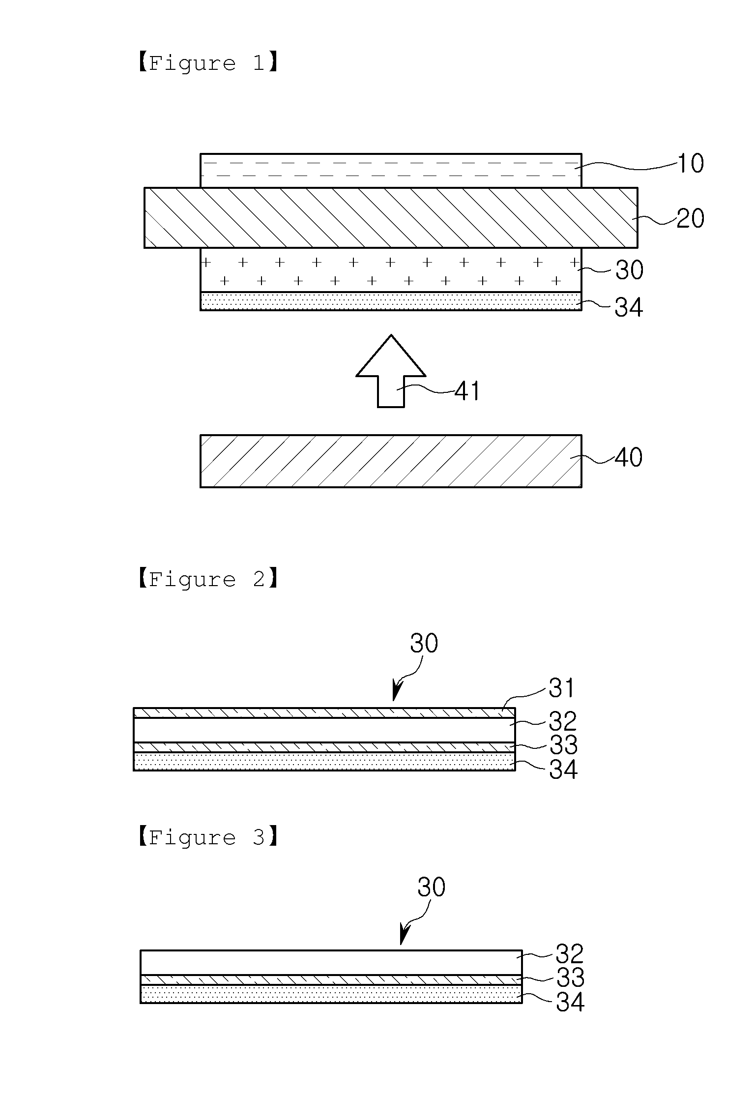
The present patent discloses a high brightness polarizing plate with improved anti-blocking characteristics and increased brightness for liquid crystal display devices. The plate includes a primer layer made of low-refractive polymer resin and fine hollow particles. The primer layer prevents the scattering of light and blocks the film during the manufacturing process. The resulting display device has better brightness and is cost-effective to manufacture.

Problems solved by technology

However, the proposed method may result in a decrease in the degree of polarization.
However, these techniques require additional processes and relatively expensive materials.
Due to such a reflection of light, the amount of light emitted from the backlight unit and incident on the lower polarizing plate is reduced to result in a decrease in brightness.
Although the existing brightness improving methods described above can be used to increase light use efficiency, the existing brightness improving methods can not be used to prevent a decrease in brightness such as that caused by an air gap.

Method used


Image

  • High brightness polarizing plate and liquid crystal display device including the same
  • High brightness polarizing plate and liquid crystal display device including the same

Examples


manufacturing example 1

Primer Layer Coating Solutions

[0114](1) Primer Layer Coating Solution A

[0115]2.53 g of a water-dispersible polyurethane resin (aliphatic polycarbonate diol type CK-PUD-PF by Chokwang Paint Corporation, solid content: 30%, refractive index: 1.50), 3.45 g of water-dispersible hollow silica (by Japan JGC Catalysts and Chemicals, solid content: 8.8%, refractive index: 1.29), and 14.01 g of pure water were mixed to prepare a coating solution A having a total solid content of 5% (30 parts by weight of the water-dispersible hollow silica for every 100 parts by weight of the water-dispersible polyurethane resin).

[0116](2) Primer Layer Coating Solution B

[0117]2.33 g of a water-dispersible polyurethane resin (aliphatic polycarbonate diol type CK-PUD-PF by Chokwang Paint Corporation, solid content: 30%, refractive index: 1.50), 3.18 g of water-dispersible hollow silica (by Japan JGC Catalysts and Chemicals, solid content: 8.8%, refractive index: 1.29), and 14.48 g of pure water were mixed to p...

manufacturing example 2

Adhesive Composition

[0126]An adhesive composition was prepared by mixing 20 g of 3,4-epoxycyclohexylmethyl-3,4-epoxycyclcohexanecarboxylate (Celloxide 2021P by Dice), 20 g of 1,4-cyclohexanedimethanol diglycidyl ether, 45 g of 3-ethyl-3-[(3-ethyloxetane-3-yl)methoxymethyl]oxetane (oxt-221 by Toagosei), and 5 g of triacrylsulfonium hexafluorophosphate (UVI-6992 by Dow Chemical).

example 1

[0127]A non-stretched acrylic film having a width of 800 mm was formed of a poly(cyclohexyl maleimide-co-methylmethacrylate) resin (PMMA830HR by LGMMA Corporation) under process conditions of 250° C. and 250 rpm by using a T-die film forming machine. Then, the acrylic film was stretched at 135° C. in an MD direction by a factor of 1.8. The acrylic film stretched in the MD direction was corona-treated at 50 W / m2 / min. Then, the acrylic film was coated with the primer coating solution A by using Mayer bar #3 and was dried by blowing 90° C. air for 3 minutes. Thereafter, the acrylic film was stretched at 135° C. in a TD direction by a factor of 2.4 so as to form an acrylic protective film (having a thickness of 50 μm) including a 300 nm thick primer layer on one side thereof.

[0128]The adhesive composition prepared in the above was applied to the other side of the acrylic protective film opposite the side on which the primer layer was formed, and a polarizer (PVA device) was disposed on ...


PUM

PropertyMeasurementUnit
Thicknessaaaaaaaaaa
Thicknessaaaaaaaaaa
Percent by massaaaaaaaaaa

Abstract

There are provided a high brightness polarizing plate and a liquid crystal display device including the high brightness polarizing plate as a lower polarizing plate. The high brightness polarizing plate includes: a polarizer; and a protective film disposed on a side of the polarizer, wherein the protective film faces a backlight unit, and a primer layer including a low-refractive polymer resin and fine hollow particles is formed on a side of the protective film opposite to a side thereof facing the polarizer.

Description

TECHNICAL FIELD[0001]The present disclosure relates to a high brightness polarizing plate and a liquid crystal display device including the high brightness polarizing plate, and more particularly, to a high brightness polarizing plate having superior anti-blocking characteristics while allowing for increases in the brightness of a liquid crystal display device, and a liquid crystal display device including the high brightness polarizing plate.BACKGROUND ART[0002]Liquid crystal display devices have recently been used in a wide range of devices including small electronic devices such as cellular phones as well as in large electronic devices, such as personal computers and televisions, and the application range thereof has been gradually widened. Since such Liquid crystal display devices are not self-luminous, generally, a light source such as a backlight unit is disposed at one side of a lower polarizing plate located below a liquid crystal cell, and light emitted from the light sourc...

Claims


Application Information

Patent Timeline
IPC IPC(8): G02B5/30G02F1/1335G02B1/14
CPCG02B5/3025G02F1/133528G02B1/14C08J5/18G02B5/30G02F2201/38G02F1/133567G02F1/1335C08K3/36G02F1/1336
Inventor HONG, KYUNG-KIJUNG, JAE-HOPARK, JUN-WUKLEE, BYUNG-MINGSHIM, JAE-HOONYOO, JE-HYUK
Owner LG CHEM LTD
Learn More