Precision bandgap reference

a bandgap reference and precision technology, applied in the field of precision bandgap reference circuits, can solve the problems of affecting the value of the reference voltage, and the error of the bandgap voltag

Inactive Publication Date: 2016-09-15
QUALCOMM INC
View PDF9 Cites 28 Cited by
  • Summary
  • Abstract
  • Description
  • Claims
  • Application Information

AI Technical Summary

Benefits of technology

[0008]In one aspect, a bandgap reference circuit is provided. The bandgap reference circuit includes: a core bandgap module configured to produce a bias control for biasing a transistor to produce a proportional to absolute temperature current; a trimming module including a diode device, a transistor configured to supply a proportional to absolute temperature current based on the bias control, a resistor having a first terminal coupled to the transistor and a second terminal coup in a him and led to the diode device, and a trim digital-to-analog converter having an output coupled to the first terminal of the resistor, wherein the trim digital-to-analog converter is configured to source or sink an amount of current based on a trim control; and an output buffer configured to buffer the first terminal of the resistor to produce a reference voltage output.

Problems solved by technology

However, process variations (including mismatches between like circuit elements) can impact the value of the reference voltage.
This input offset voltage is amplified and creates an error in the bandgap voltage.
Variations in resistor values and transistor characteristics also cause errors in the bandgap voltage.
Implementing bandgap reference circuits in advanced process nodes is difficult.
Characteristics of advanced process nodes that impair performance of bandgap reference circuits include greater process variation, limited choice of transistor sizes, and lower supply voltages.
Each of these techniques has associated disadvantages (e.g., larger circuit area, increased power dissipation, increased noise on the reference voltage) and may still produce unsatisfactory results.

Method used


Image

  • Precision bandgap reference
  • Precision bandgap reference
  • Precision bandgap reference

Examples


Embodiment Construction

[0019]The detailed description set forth below, in connection with the accompanying drawings, is intended as a description of various configurations and is not intended to represent the only configurations in which the concepts described herein may be practiced. The detailed description includes specific details for the purpose of providing a thorough understanding of the various concepts. However, it will be apparent to those skilled in the art that these concepts may be practiced without these specific details. In some instances, well-known structures and components are shown in simplified form in order to avoid obscuring such concepts.

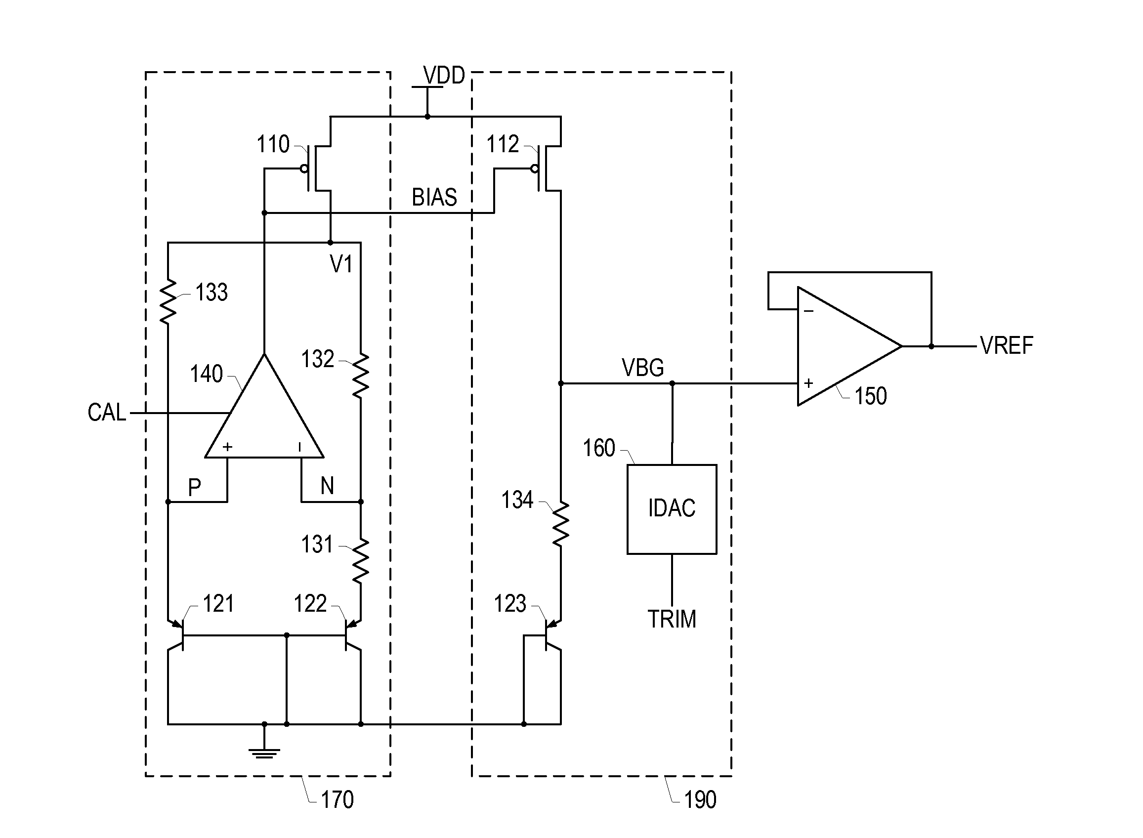
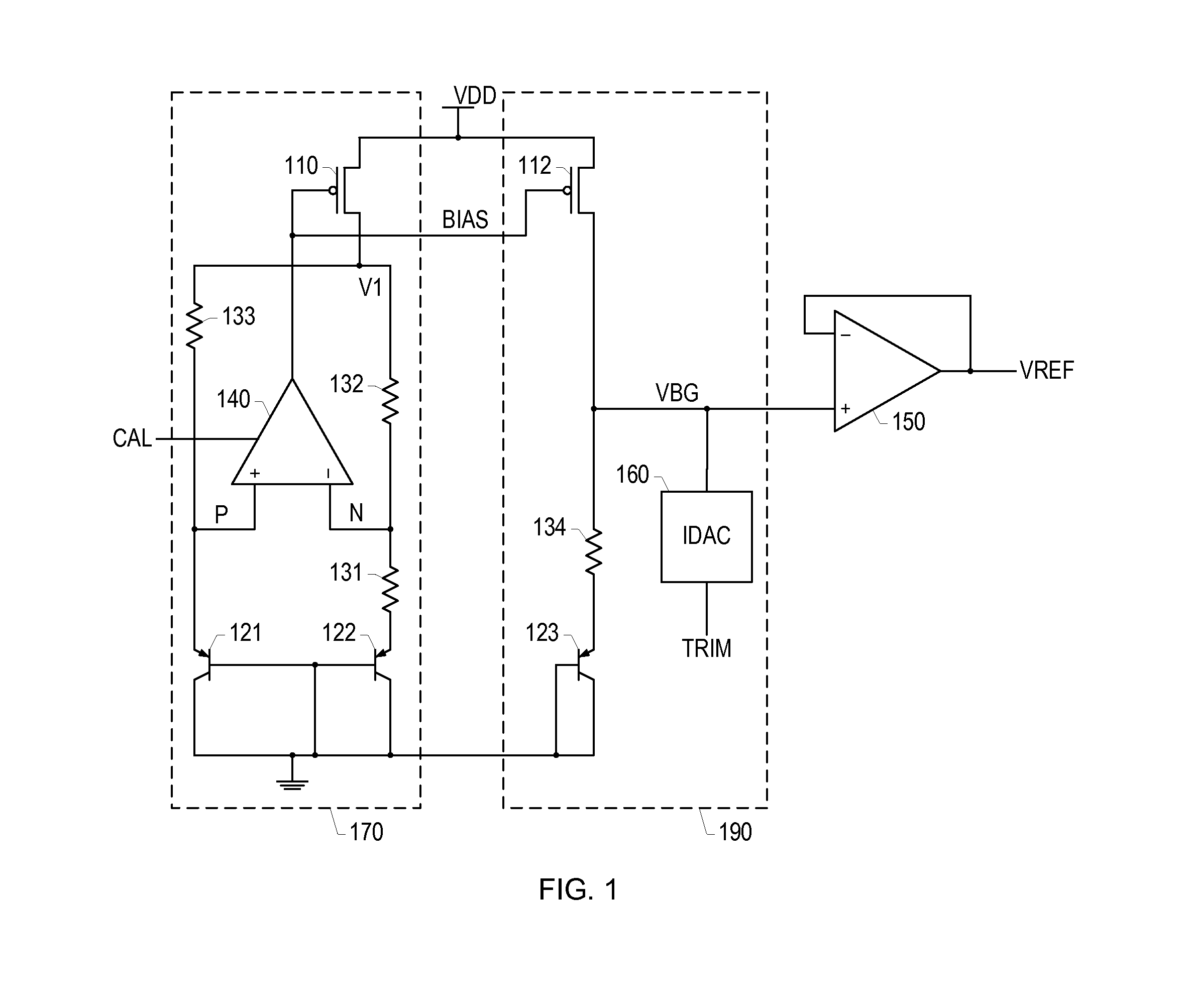
[0020]FIG. 1 is a schematic diagram of a bandgap reference circuit according to a presently disclosed embodiment. The bandgap reference circuit may be implemented, for example, in a complementary metal oxide semiconductor (CMOS) system-on-a-chip (SoC) integrated circuit (IC). The bandgap reference circuit is suitable for use in an advanced process n...


PUM


Abstract

Systems and methods for producing reference voltages are disclosed. An example bandgap reference circuit includes a core bandgap module that produces a bias control for biasing the gate of a transistor to produce a proportional to absolute temperature current. The core bandgap module may use an operational amplifier that uses auto-calibration to reduce its input offset voltage. A trimming module uses the bias control to produce a proportional to absolute temperature current that is combined with a trim current and supplied to a resistor and diode to produce a trimmed bandgap voltage. The trimmed bandgap voltage is buffered to produce a reference voltage output. The trim current may be set based on a room temperature measurement of the reference voltage output.

Description

BACKGROUND[0001]1. Field[0002]The present invention relates to electronic circuits and, more particularly, to precision bandgap reference circuits.[0003]2. Background[0004]A building block of many electronic circuits is a reference voltage that exhibits little dependence on supply voltage, little dependence on fabrication process conditions, and little dependence on temperature. Bandgap reference circuits are commonly used to provide reference voltages. The reference voltage output from a bandgap reference circuit can be used, for example, in an analog-to-digital converter to accurately quantify an input, in a digital-to-analog converter to define the output full-scale range, and in a power supply to accurately control a supplied voltage level.[0005]Bandgap reference circuits create a temperature-stable reference voltage by adding a diode voltage, which has a negative temperature coefficient (also referred to as complementary to absolute temperature (CTAT)), to a voltage that is pro...

Claims


Application Information

Patent Timeline
Patent Type & Authority Applications(United States)
IPC IPC(8): G05F3/26
CPCG05F3/267G05F3/30
Inventor WONG, MONG CHITDANG, NAM VANJAIN, RAJEEVWANG, BO-RENSHAHROKHINIA, SASSAN
Owner QUALCOMM INC
Why Eureka
Try Eureka