

Secondary battery
a rechargeable battery and secondary battery technology, applied in the field of rechargeable batteries, can solve the problem of limited lithium content in the world
- Summary
- Abstract
- Description
- Claims
- Application Information
AI Technical Summary
Benefits of technology
Problems solved by technology
Method used
Image

Examples
exemplary embodiment 1
Manufacturing of Rechargeable Battery
[0118]Manufacturing of Cathode Portion
[0119]Carbon paper (Fuel Cell Store, 2050-A) was used as a current collector. Seawater was injected into a cathode container and then the current collector was impregnated in the seawater such that a cathode portion was manufactured.
[0120]A porosity of the carbon paper was 28 μm.
[0121]Manufacturing of Anode Portion
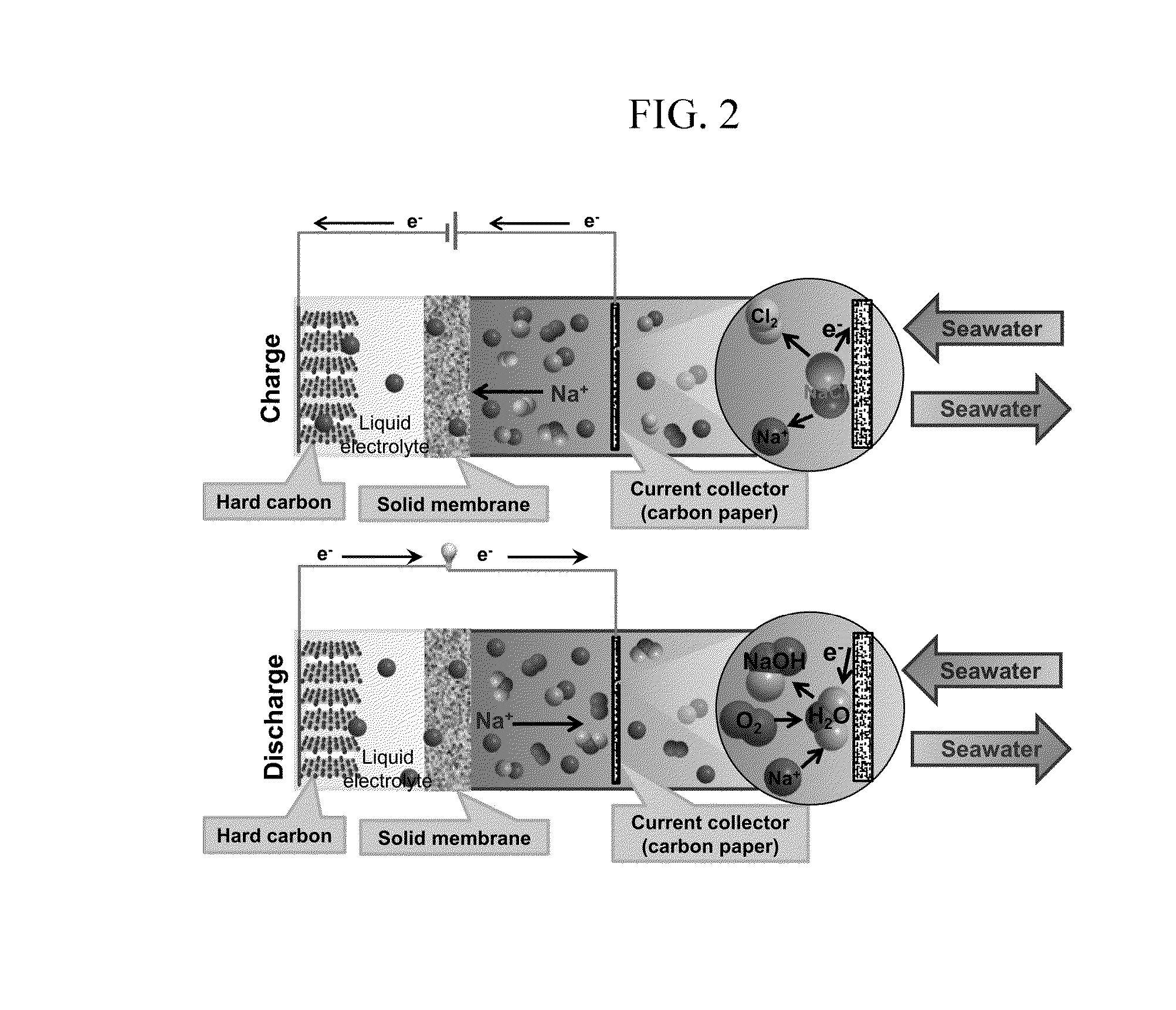
[0122]1) FIG. 2 is a schematic diagram of a seawater battery formed of a hard carbon anode. Stainless steel (McMASTER) was used as a current collector. On the current collector, hard carbon (MTI): super P carbon black (TIMCAL), which is a conductive material: poly (terofluoroethylene), which is a binder were mixed with a ratio of 70:20:10 (wt %) to form an anode active material layer such that an anode was manufactured.
[0123]An organic electrolyte is injected into an anode container and then the manufactured anode was impregnated therein.
[0124]Three of organic electrolytes were used, and the first o...
experimental example 1
Battery Characteristic Evaluation
[0131]Charge and Discharge Characteristics Evaluation
[0132]FIG. 4 shows variation data of voltage data of the battery according to Exemplary Embodiment 1 and salt in seawater when the battery is being discharged.
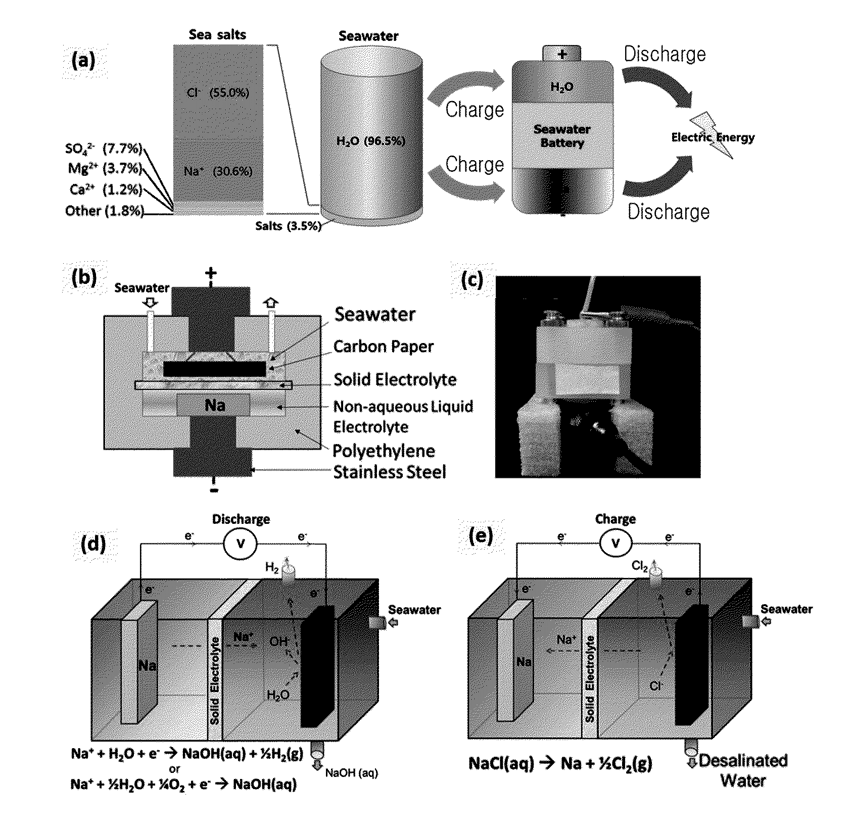
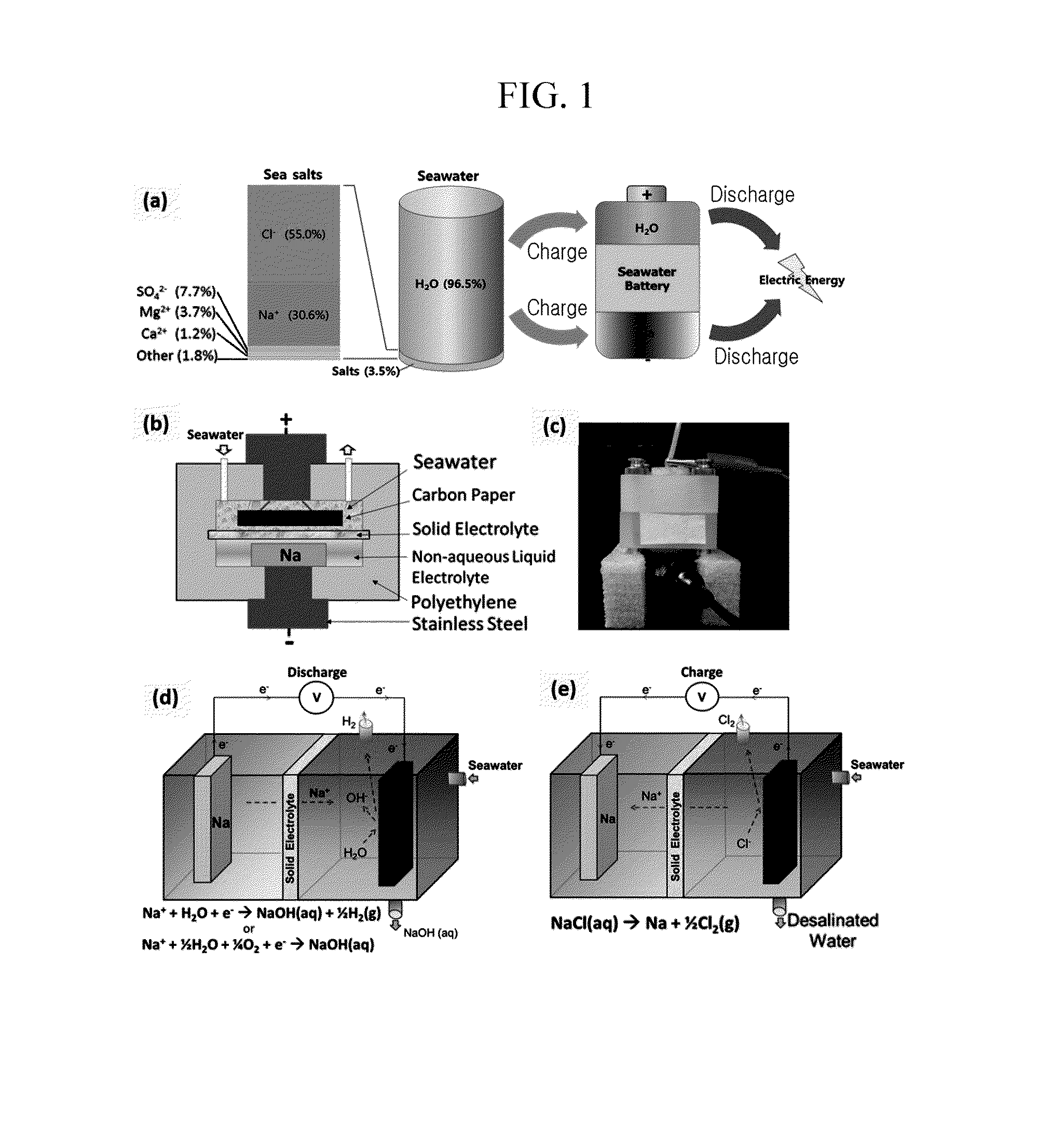
[0133]When the battery is charged, Na+ ion is dispersed through a NASICON solid electrolyte and thus moves to the anode portion, and in this case, Cl2 gas is generated.
[0134]When the battery is charged, generation of O2 (E=3.94 V) gas is thermodynamically preferred than generation of Cl2 (E=4.07 V) gas, but in the seawater battery of the above-stated exemplary embodiment, Cl2 and O2 both are generated.
[0135]Due to high over-potential of O2, generation of Cl2 is higher than generation of O2 in an electrolyte reaction in seawater.
[0136]When the battery is discharged, O2 dissolved in seawater is reduced since it forms NaOH.
[0137]When the battery is charged, lop analysis and ion chromatography analysis were performed in order to determine variati...
exemplary embodiment 2
Manufacturing of Rechargeable Battery
[0185]Manufacturing of Cathode Portion
[0186]Carbon paper (Fuel Cell Store, 2050-A) was used as a cathode current collector. Seawater was injected into a cathode container and then the cathode current collector was impregnated in the seawater such that a cathode portion was manufactured.
[0187]A porosity of the carbon paper was 28 μm.
[0188]Manufacturing of Anode Portion
[0189]Stainless steel (McMASTER) was used as a current collector. On the current collector, hard carbon (MTI): super P carbon black (TIMCAL), which is conductive material: poly (terofluoroethylene), which is a binder, were mixed with a ratio of 70:20:10 (wt %) to form an anode active material layer such that an anode was manufactured.
[0190]An organic electrolyte is injected into the anode portion and then the manufactured anode was impregnated therein.
[0191]The organic electrolyte was manufactured by mixing ethylene carbonate (EC):diethylene carbonate (DEC) (1:1 volume ratio) and 1M ...
PUM
| Property | Measurement | Unit |
|---|---|---|
| conductive | aaaaa | aaaaa |
| ion conductive | aaaaa | aaaaa |
| porosity | aaaaa | aaaaa |
Abstract
Description
Claims
Application Information