Nose cone structure for pylon of aircraft with wing-hung layout

a technology of pylons and aircraft, which is applied in the direction of fuselage insulation, aircraft power plant components, aircraft power plants, etc., can solve the problems of adverse effect on the wing, adverse effect on the safety and economy of flight of aircraft, increase the weight of aircraft, increase the manufacturing cost and maintenance cost of aircraft, etc., to reduce resistance, improve aerodynamic performance, and optimize the passageway area

Inactive Publication Date: 2016-09-22
COMAC +1
View PDF8 Cites 43 Cited by
  • Summary
  • Abstract
  • Description
  • Claims
  • Application Information

AI Technical Summary

Benefits of technology

[0012]In order to overcome the above defects existing in the prior art, the present invention provides a nose cone structure for a pylon of an aircraft with a wing-mounted layout, especially a rear nose cone structure having enough internal space without additionally adding part nose cone on the surface behind the rear portion of the pylon. The present invention enables the air flow on the surface of the nose cone of the pylon to avoid generating a flow separation, thereby decreasing the resistance, reducing the weight, reducing the adverse effect caused by the engine mounted to the wing and enhancing the performance of the airplane.
[0013]To this end, according to one embodiment, the present invention provides a nose cone structure for a pylon of an aircraft with a wing-mounted layout, the nose cone structure comprising a front nose cone located in front of a wing leading edge and a rear nose cone located behind the wing leading edge, wherein at least part of the rear nose cone is modeled and shaped by cross section control segments, and comprises at least one group of latitudinal position control segments and at least one group of longitudinal position control segments. Through formation of the rear nose cone of the pylon by the position control segments, the invention can control the pylon with the horizontal and longitudinal curvatures and the angle of the rear edge of the latitudinal position control segments at the position adjacent to the wing, thereby reducing the interference of the nose cone of the pylon on the wing.
[0014]According to one embodiment, a trailing edge line of the rear nose cone has a convex arc shape projecting towards a trailing edge of a wing. This arrangement can ensure the internal space needed by the rear nose cone and enable the profile of the rear nose cone to have a more smooth transition from a wider position to the trailing edge line in the direction of the air flow, thereby helping to suppress the air flow separation of the surface of the pylon.
[0016]According to one embodiment, the trailing edge line of the rear nose cone directly contacts a surface of a nozzle of an engine. In this way, the present invention can reduce the bottom area of the rear nose cone of the pylon in the wake flow of the engine even to be zero, and thereby reducing the resistance to a large extent and decreasing the usable area of the thermal insulation material.
[0020]Through formation of the rear nose cone of the pylon by the horizontal and longitudinal position control segments, the invention can conduct pylon design only through curvature control on the rear nose cone of the pylon, and can optimize the passageway area of the space between the pylon / wing / engine nacelle by controlling the rear nose cone curvature of the pylon without deflection of the rear portion of the pylon. Additionally, the present invention has a trailing edge line protruding towards the trailing edge of the pylon, meanwhile the trailing edge line of the pylon directly contacts the surface of the nozzle of the engine, thus the area of the surface of the nose cone of the pylon immersed in the wake flow of the engine is reduced, thereby reducing the resistance, improving the aerodynamic performance, reducing the adverse effect on the wing, increasing the internal space of the nose cone of the pylon, avoiding the increasing of the weight of the airplane body, and decreasing the manufacturing cost and the maintenance cost of the aircraft.

Problems solved by technology

As for the aircraft in which an engine is mounted below the wing (i.e., an aircraft with a wing-mounted layout), the upper surface of the wing is not provided with a relatively large protruding part, while the lower surface of the wing contacts a pylon of the engine and is susceptible to the airflow surrounding a pneumatic surface of the nose cone of the pylon.
If the lower surface of the wing suffers significant adverse effect from the pneumatic surface of the nose cone of the pylon, the airflow on the lower surface of the wing trends to be separated and it is adverse for the safety and economy of the flight of the aircraft.
The width constraint and the adverse curvature distribution of the pylon caused by the width constraint have an adverse effect on the wing.
But this arrangement will add airframe structure parts and actuating structures, thereby increasing the weight of the aircraft as well as the manufacturing cost and the maintenance cost of the aircraft.
However, the nose cone arranged in the position adjacent to the wing will decrease the area of the lower surface of the wing, reduce the lift force of the aircraft, and reduce the carrying capacity of the aircraft.
This solution is not suitable for the initial stage of the design of the aircraft.
However, the change of the wing will affect most of the design parameters of the aircraft, and result in large change of the design, thus the designer should avoid the change of the wing as much as possible.
If the improvement for the subsequent aircraft in a certain series of aircrafts applies this solution, it will delay the airworthiness certification process.
However, the added spoiler generates an additional resistance, and this spoiler works in the wake flow of the engine and needs to be formed by high temperature resistant material, which increases the manufacturing costs.
The additional actuators needed by the spoiler will increase the maintenance cost of the aircraft, thus this solution is also not suitable for the initial stage of the design of the airplane.
If the installing space is relatively small, this solution cannot optimize its value.
Because if the installing space is relatively small, the cross section of the pylon cannot have an integral wing shape, and thus the deflection of the cross section of the pylon in the form of an integral wing shape cannot be obtained.
Moreover, this solution may have an adverse effect on the airflow towards the wingtip at the jointing position between the pylon of the aircraft and the front edge of the wing.

Method used


Image

  • Nose cone structure for pylon of aircraft with wing-hung layout
  • Nose cone structure for pylon of aircraft with wing-hung layout
  • Nose cone structure for pylon of aircraft with wing-hung layout

Examples


Embodiment Construction

[0025]The following description will describe the nose cone structure of the pylon in an aircraft with a wing-mounted layout. In the following description, some orientation terms, such as “left”, “right”, “top”, “bottom”, “front” , “back”, “guide”, “forwards”, and “backwards”, are used with reference to the directions shown in the drawings, and the orientation terms are used as example rather than limitation. However, it should be appreciated that the described embodiments are only used to illustrate the special form for implementing and applying the present invention in an exemplary manner, rather than limit the scope of the present invention.

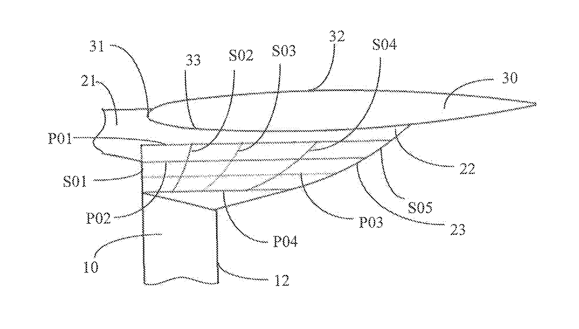
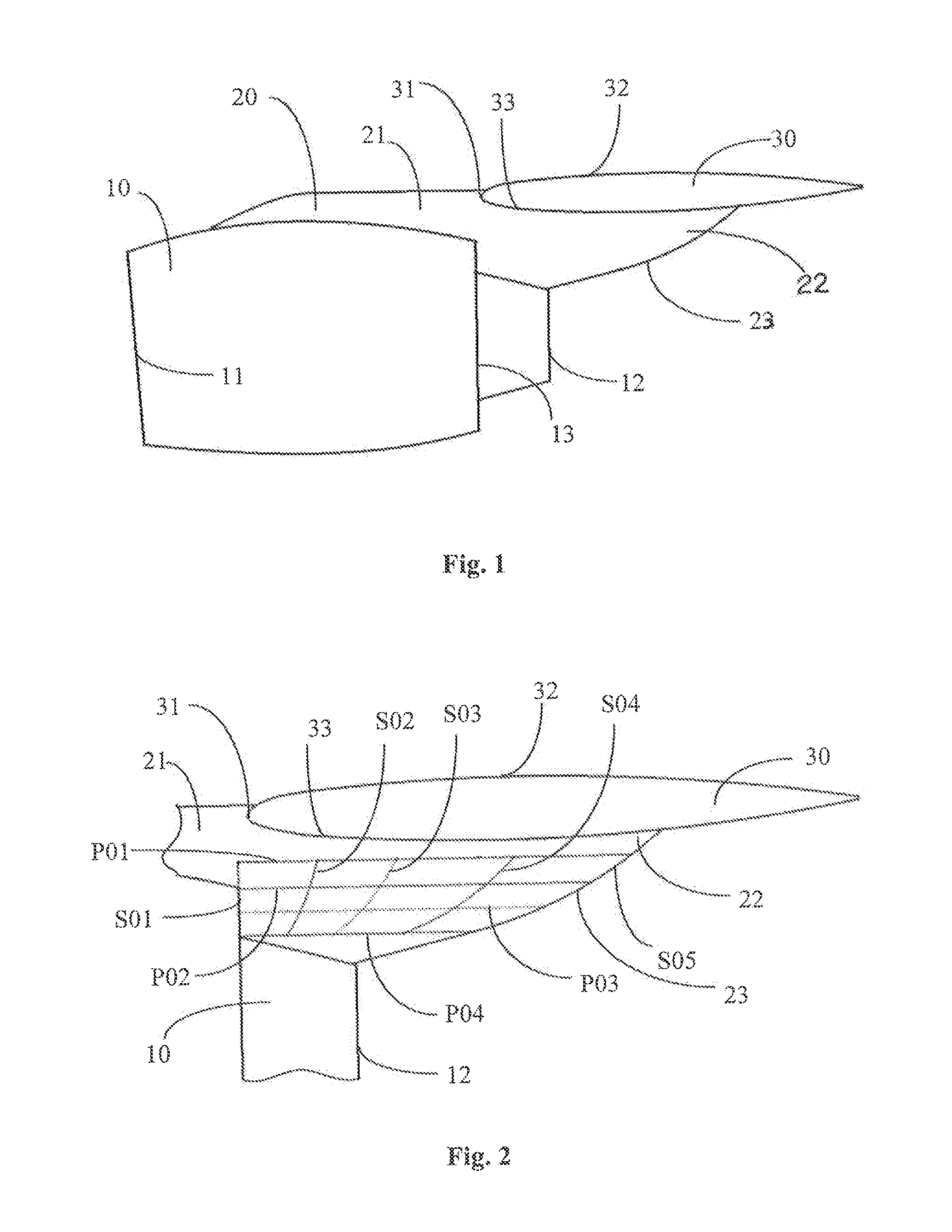
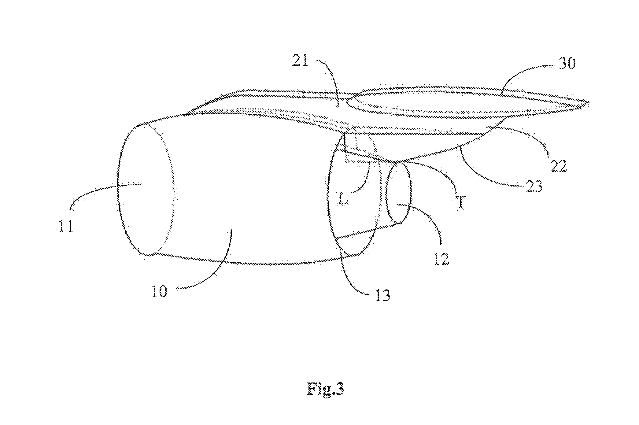
[0026]Referring to FIGS. 1 and 2, according to one preferred embodiment of the present invention, the improvement for the design of the nose cone structure of the pylon is achieved by the sectional control segments modeling for at least one part of the rear nose cone of the pylon. For the person skilled in the art, the modeling technology is w...


PUM


Abstract

An aircraft with a wing-hung layout has a nose cone structure for a pylon. A front nose cone is located in front of a wing leading edge, and a rear nose cone is located behind the wing leading edge. At least a part of the rear nose cone is modeled and shaped by cross section control lines and has at least one group of horizontal position control lines and at least one group of longitudinal position control lines. The rear nose cone of the pylon is shaped by horizontal position control lines. By controlling the rear nose cone curvature of the pylon the passageway area of the space between the pylon / wing / engine nacelle is optimized without deflection of the rear portion of the pylon.

Description

CROSS-REFERENCE TO RELATED APPLICATIONS[0001]This application claims priority to International Application Serial No. PCT / CN2014 / 1085417, filed Aug. 28, 2014, which claims priority to Chinese Application No. 201310506992.0, filed Oct. 24, 2013. International Application Serial No. PCT / CN2014 / 085417 is hereby incorporated herein in its entirety for all purposes by this reference.FIELD OF THE DISCLOSURE[0002]The present invention generally relates to the field of aircraft aerodynamic configuration design, and more particularly to a nose cone structure, especially a rear nose cone structure, for a pylon of an aircraft with a wing-mounted layout.BACKGROUND OF THE DISCLOSURE[0003]During the flight of the aircraft, both an upper surface and a lower surface of the wing can generate a lift force. Generally, during the cruising flight, it should be ensured that flow separation is not generated on the upper surface and the lower surface of the wing. As for the aircraft in which an engine is m...

Claims


Application Information

Patent Timeline
Patent Type & Authority Applications(United States)
IPC IPC(8): B64D29/02B64C7/02B64C23/00
CPCB64D29/02B64C1/40B64C7/02B64C23/00B64D27/00Y02T50/40
Inventor CHEN, YINGCHUNZHANG, MIAOYU, ZHEHUIZHANG, MEIHONGXUE, FEILIU, TIEJUNZHANG, DONGYUNZHOU, FENGMA, TULIANGZHAO, BINBIN
Owner COMAC
Why Eureka
Try Eureka