Fiber coupled modular laser system

a laser system and fiber technology, applied in the direction of laser details, active medium materials, active medium shape and construction, etc., can solve the problems of insufficient or inconvenient space availability

Active Publication Date: 2016-09-22
ADVANCED OPTOWAVE
View PDF2 Cites 4 Cited by
  • Summary
  • Abstract
  • Description
  • Claims
  • Application Information

AI Technical Summary

Problems solved by technology

The available space is often not suitable or not enough for the position sett

Method used


Image

  • Fiber coupled modular laser system
  • Fiber coupled modular laser system
  • Fiber coupled modular laser system

Examples


Embodiment Construction

[0013]In the following description, numerous specific details are set forth in order to provide a thorough understanding of the present invention. It will be apparent, however, to one having ordinary skill in the art that the specific detail need not be employed to practice the present invention. In other instances, well-known materials or methods have not been described in detail in order to avoid obscuring the present invention.

[0014]Reference throughout this specification to “one embodiment” or “an embodiment” means that a particular feature, structure or characteristic described in connection with the embodiment is included in at least one embodiment of the present invention. Thus, appearances of the phrases “in one embodiment” or “in an embodiment” in various places throughout this specification are not necessarily all referring to the same embodiment. Furthermore, the particular features, structures or characteristics may be combined in any suitable combinations and / or sub-com...


PUM


Abstract

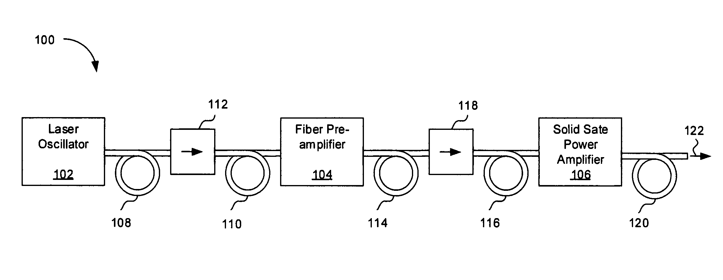
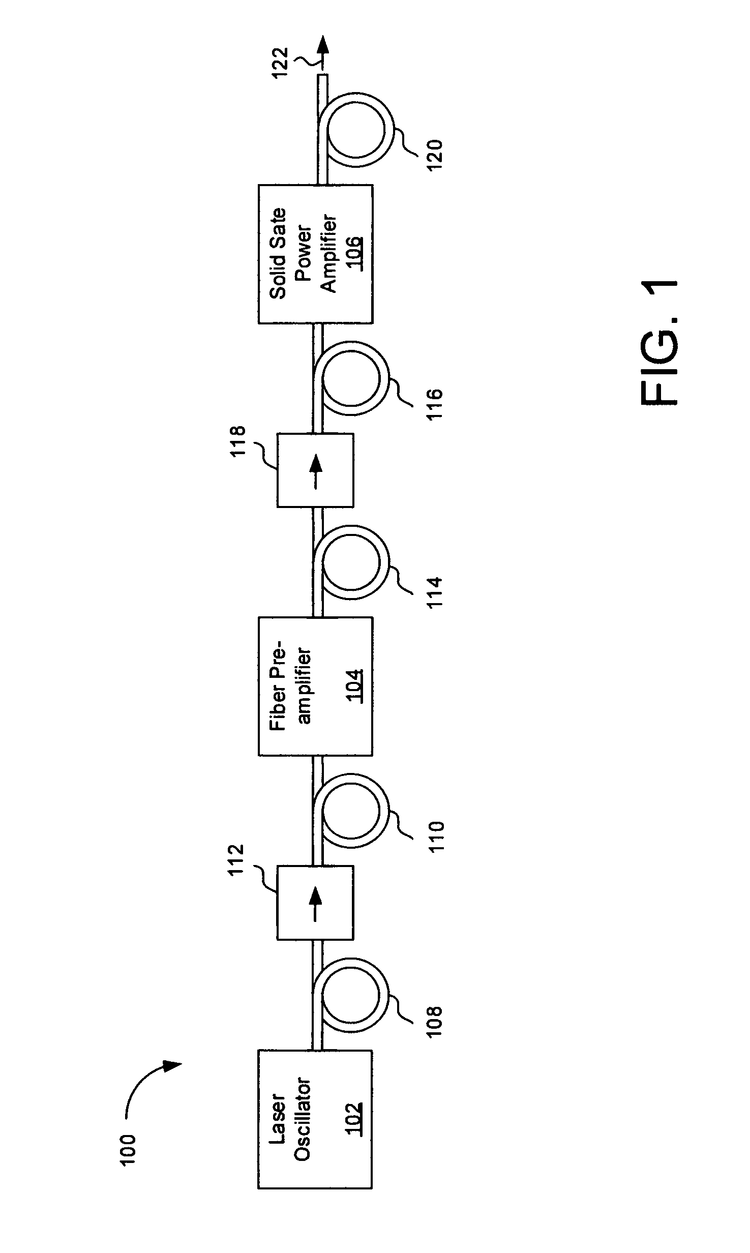
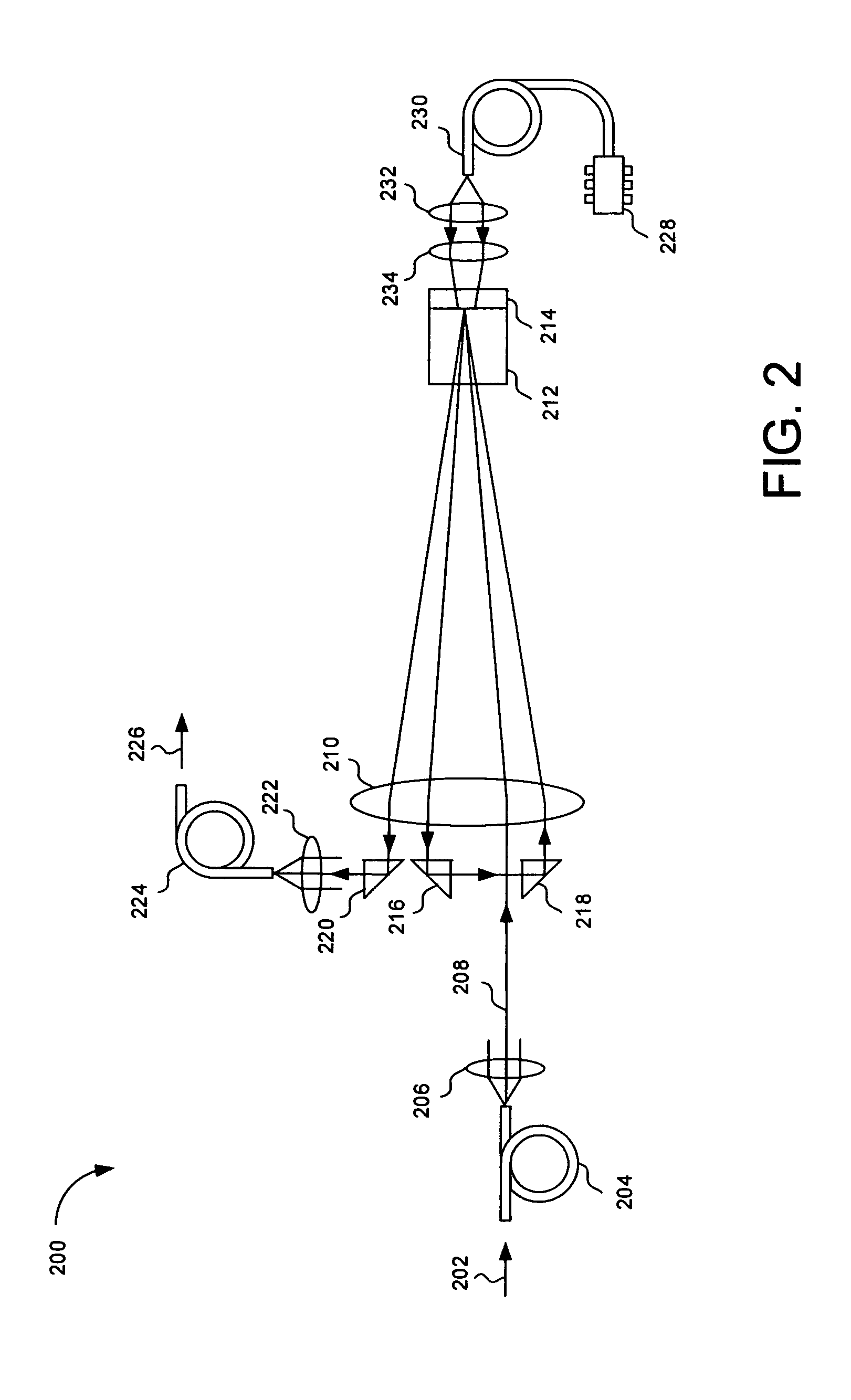
A fiber coupled modular laser system comprises a laser oscillator, at least one fiber pre-amplifier, and at least one free space solid state power amplifier. The output of the laser oscillator is fiber coupled with the input of the at least one fiber pre-amplifier or the at least one free space solid state power amplifier. The output or the input of the at least one fiber pre-amplifier is fiber coupled with the input or the output of the at least one free space solid state power amplifier.

Description

FIELD OF THE INVENTION[0001]This invention relates to fiber coupled modular laser systems and more specifically to fiber coupled modular laser systems comprising laser oscillators, fiber pre-amplifiers, and free space solid state power amplifiers.BACKGROUND OF THE INVENTION[0002]High power lasers are used for laser cutting, welding, and folding of metals and polymers. High peak power and nanosecond pulses enable effective marking and engraving. The additional power and better beam quality provide cleaner cut edges and faster cutting speeds. A high power laser system may comprise an oscillator, multiple stages of fiber pre-amplifiers, and free space solid state power amplifiers. The oscillator sets the laser's wavelength, pulse width, and repetition rate, while the fiber amplifiers boost the laser power to a required level. The last module of the high power laser includes a free space solid state power amplifier for power amplifying the laser beam received from the fiber pre-amplifie...

Claims


Application Information

Patent Timeline
IPC IPC(8): H01S3/091H01S3/16H01S3/10H01S3/067
CPCH01S3/091H01S3/06758H01S3/10023H01S3/16H01S3/0675H01S3/2375H01S3/0602H01S3/06754H01S3/09415H01S3/113H01S3/2341
Inventor ZHAO, XIAOJIEHE, CHUN
Owner ADVANCED OPTOWAVE
Why Eureka
Try Eureka