System and method for dispensing UV treated materials

a technology of uv treatment and dispensing system, which is applied in the direction of water treatment compound, water treatment parameter control, transportation and packaging, etc., can solve the problems of reducing the efficiency of the bulb in colder temperatures, and reducing the life of the bulb, so as to reduce the formation of contaminants in the intake portion and storage portion.

Inactive Publication Date: 2016-09-29
LARQ INC
View PDF9 Cites 13 Cited by
  • Summary
  • Abstract
  • Description
  • Claims
  • Application Information

AI Technical Summary

Benefits of technology

[0007]Embodiments of the present invention include a water dispenser comprising an intake portion and a storage portion. Sidewalls of the intake portion and the storage portion may be coated with one or more photo-reactive materials that are reactive to UV illumination, and include one or more UV light emitting diodes (LEDs) that output light within the UV-A spectral range (UV-A, UV-B and UV-C are defined as: UV-A from 400 nm to 315 nm, UV-B from 315 nm to 280 nm, and UV-C from 280 nm to 100 nm). In various embodiments, the UV-LEDs output UV light, strike the reactive materials, and generate free-radicals from the water and vapor, within the region of the sidewalls. In turn, the free-radicals attack contaminants formed on and in the proximity from the sidewalls, such as mold, mildew, or the like, prevent such formation on the sidewalls, and the like. Accordingly, formation of contaminants within the intake portion and storage portion are reduced.
[0008]Additionally, in various embodiments, the water dispenser may include a sanitation portion that receives water from the storage portion. This portion may include an open-ended volumetric region formed of material that is UV reflective and one or more UV-LEDs that output light within the UV-B and / or UV-C (hereby and below referred to as the UV-B and / or C LEDs) range. In various embodiments, the UV-LEDs output UV light directly or indirectly to the water within the volumetric region to attack contaminants within the water. Accordingly, contaminants (including pathogens) with the water are reduced, and the water is made more safe for consumption.
[0009]In some embodiments, various timers and power adjustment parameters may be used to control the UV-A-LEDs and the UV-B and / or C-LEDs. In such embodiments, one or more sensors may be included to determine a contamination level of the water, for example, and the output parameters of the UV-LEDs may be adjusted, accordingly. For example, in some examples, a voltage magnitude may be changed, a duty cycle may be changed, an on time may be changed, and the like. As an example of this, for highly contaminated water, the power applied to UV-C-LEDs may be increased, and the duration of the UV-B and / or C illumination of the water within the sanitation portion may also be increased.

Problems solved by technology

A problem recognized by the inventors is that although water stored in water bottles may be relatively safe to drink, the exterior portions of the water bottles may have many types of contaminants.
These contaminants may originate from the water bottle factory, from road dirt during transport of the water bottle, from storage of the water bottle prior to use, and the like.
Such a concept, however, has many drawbacks.
Some drawbacks include that the limited life span (1000 to 5000 hours) for mercury vapor bulbs makes it unsuitable for water dispensers that are designed for years of service; and that turning on and off a mercury vapor bulb greatly reduces the bulb's life span.
Additional drawbacks include that such bulbs do not operate efficiently in colder temperatures, such as a chilled-water storage containers.
Further, if mercury bulbs break, poisonous mercury may leech into the water, without anyone being aware of it.
For such reasons, the inventors do not believe it is practical to use vapor-based UV-lights to maintain sanitation of water dispensers.
Although such materials appear effective in reducing pathogen growth on the surfaces of such materials, it does not reduce pathogens in the water itself.

Method used


Image

  • System and method for dispensing UV treated materials
  • System and method for dispensing UV treated materials
  • System and method for dispensing UV treated materials

Examples


Embodiment Construction

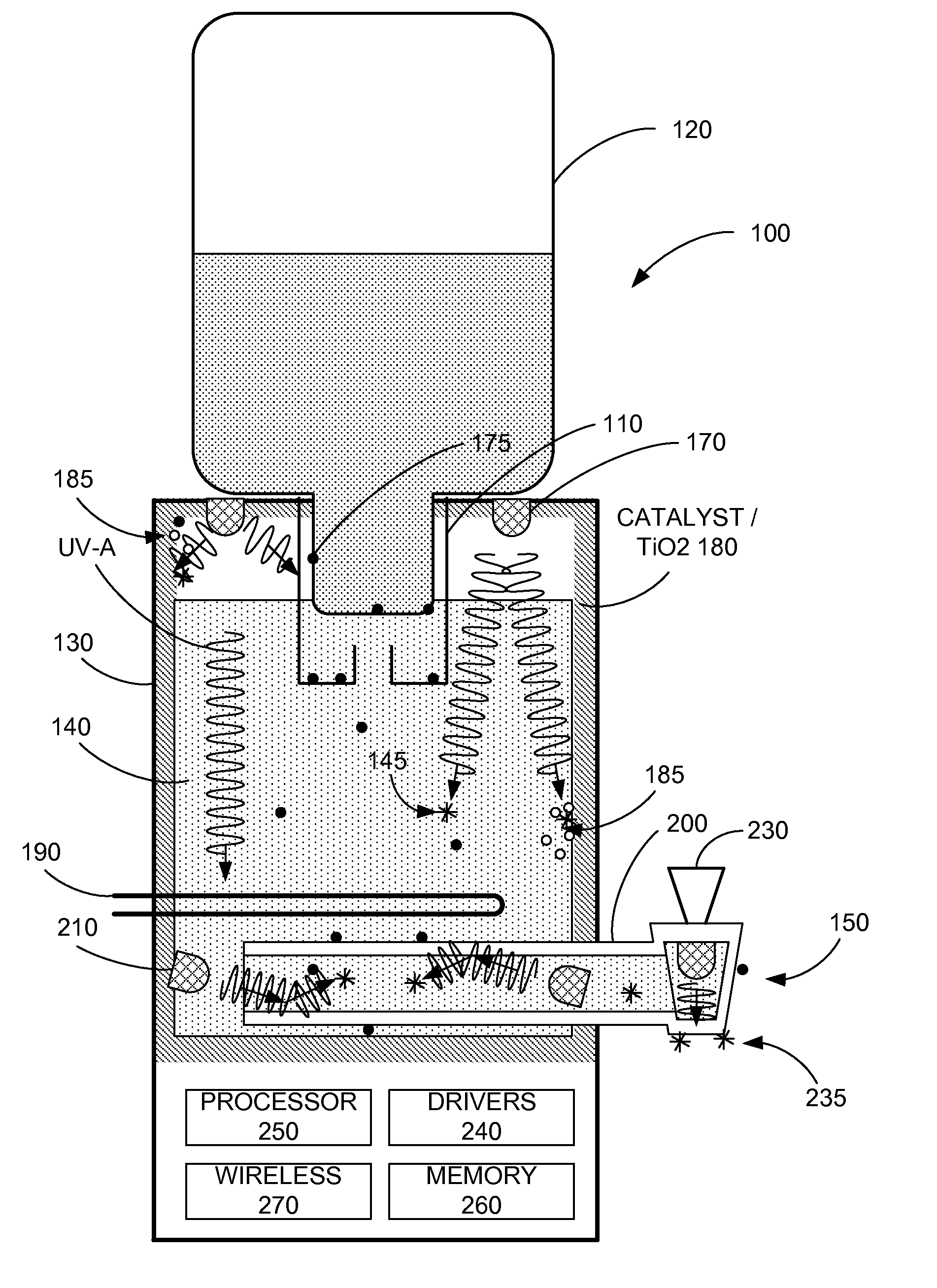
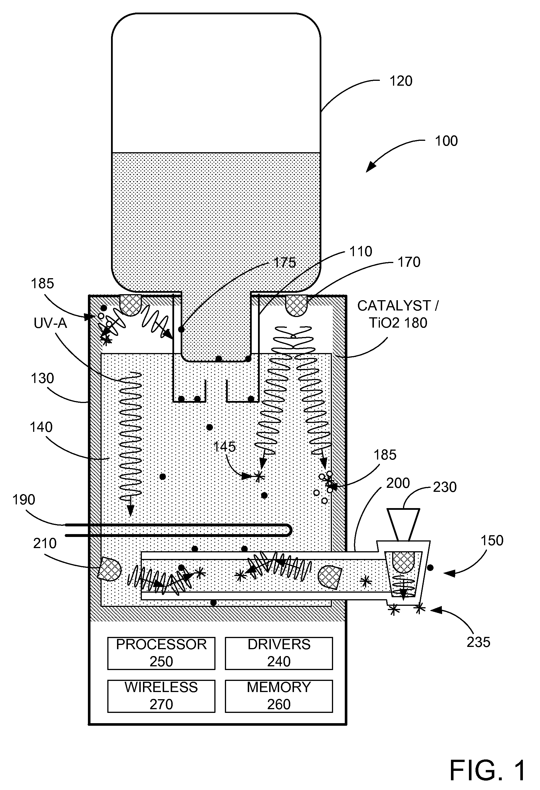
[0019]FIG. 1 illustrates a diagram of an embodiment of the present invention. More specifically, FIG. 1 is a diagram of a typical water cooler 100 found in many homes and businesses in the US and other countries. As shown, water cooler 100 includes a receiving portion 110 adapted to receive a water source (e.g. water bottle) 120, a central storage tank 130 for storage of water 140, and an output portion 150. In various embodiments, water source 120 and / or central storage tank 130 may be of any size, for example 1 cup to 10's of gallons or even larger. In some embodiments, water source 120, central storage tank 130, and output portion 150 may be located at the same physical device, or remote from each other. For example, in some embodiments, water source 120 may be a water tank in a dwelling, a municipal water supply, or the like, and a water line is connected to the central storage tank 130. Additionally, central storage tank 130 can supply liquids to one or more output portions 150...


PUM

PropertyMeasurementUnit
frequencyaaaaaaaaaa
poweraaaaaaaaaa
DC voltageaaaaaaaaaa

Abstract

A device for providing treated materials includes a storage portion comprising an enclosed region with sidewalls, an input portion and UV-LEDs, wherein the enclosed region stores material and includes a UV-responsive material, wherein the input portion receives the material, wherein the UV-LEDs provide UV-A illumination range within the enclosed region and the UV-responsive material inhibits contaminant formation upon the sidewalls in response to the UV-A illumination, and a material treatment portion having sidewalls, UV-LEDs and an output portion, wherein the sidewalls are configured to reflect UV light, wherein material treatment portion receives the material from the storage portion, wherein the UV-LEDs provide UV-B and / or UV-C illumination to treat or sanitize the material within the material treatment portion, and wherein the output portion is for providing output of the treated material.

Description

CROSS-REFERENCE TO RELATED APPLICATIONS[0001]The present invention is a continuation-in-part of U.S. patent application Ser. No. 14 / 672,077, filed Mar. 27, 2015 and claims priority to U.S. Provisional Application No. 62 / 187,169, filed Jun. 30, 2015.BACKGROUND OF THE INVENTION[0002]The present invention relates to sanitation of consumable materials. More specifically, embodiments of the present invention relate to methods and apparatus for facilitating sanitation of liquids such as water or juices and solids such as ice, or the like.[0003]A problem recognized by the inventors is that although water stored in water bottles may be relatively safe to drink, the exterior portions of the water bottles may have many types of contaminants. These contaminants may originate from the water bottle factory, from road dirt during transport of the water bottle, from storage of the water bottle prior to use, and the like. The inventors have discovered that contaminants may be introduced into the wa...

Claims


Application Information

Patent Timeline
Patent Type & Authority Applications(United States)
IPC IPC(8): A23L3/28C02F1/32
CPCA23L3/28C02F1/325C02F2303/04C02F2201/3227C02F2201/3228C02F2201/326C02F2201/3222B67D3/0032B67D3/0038B67D3/0077B67D2210/00015C02F2209/006C02F2209/008C02F2209/08C02F2209/11C02F2209/15C02F2209/20C02F2209/21C02F2209/36C02F2305/10C02F2307/10
Inventor LIAO, YITAOWALKER, ROBERTCOLLINS, DOUG
Owner LARQ INC
Why Eureka
Try Eureka