Resistive welding electrode and method for spot welding steel and aluminum alloy workpieces with the resistive welding electrode

a resistive welding electrode and spot welding technology, applied in welding/cutting media/materials, welding apparatus, manufacturing tools, etc., can solve the problems of generating heat and a tendency to retain heat for a longer time, and achieve the effect of promoting welding output efficiency and cost containment, and long operational li

Active Publication Date: 2016-09-29
GM GLOBAL TECH OPERATIONS LLC
View PDF6 Cites 22 Cited by
  • Summary
  • Abstract
  • Description
  • Claims
  • Application Information

AI Technical Summary

Benefits of technology

[0014]The greater contact area established between the weld face of the resistive welding electrode, as compared to the weld face of the second welding electrode, causes the electrical current being passed between the welding electrodes to assume a conical flow pattern in which the path of current flow expands radially from the second welding electrode to the resistive welding electrode. This results in the current density of the electrical current being greater in the steel workpiece than in the aluminum alloy workpiece. The difference in current density concentrates heat within a smaller zone in the steel workpiece as compared to the aluminum alloy workpiece, thus modifying the temperature gradients around the molten aluminum alloy weld pool during current flow. To be sure, by concentrating heat within a smaller zone in the steel workpiece adjacent to the molten aluminum alloy weld pool, the steel workpiece functions as a heat source that helps discourage the molten aluminum alloy weld pool from solidifying directionally towards the faying interface upon cessation of current flow.
[0015]The resistive welding electrode can also be used to resistance spot weld a workpiece stack-up that includes adjacent, overlapping, and contacting aluminum alloy workpieces as well as adjacent, overlapping, and contacting steel workpieces. Such broad capabilities permit the resistive welding electrode to be used in conjunction with different metal workpiece combinations, if desired, to help promote welding output efficiency and cost containment within a manufacturing setting. Moreover, across all of these potential uses, especially when used in a way that calls for pressed contact with an aluminum alloy workpiece, the resistive welding electrode exhibits a level of inertness compared to conventional copper-zirconium welding electrodes. Of particular significance, the resistive welding electrode does not metallurgically react with aluminum over the course of repeated spot welding events to form intermetallic, oxide, and / or other contaminants that have a tendency to spall or form pits in the electrode weld face if produced and not removed. This reaction inertness reduces the need to redress the weld face of the resistive welding electrode and helps the electrode maintain a long operational lifetime.

Problems solved by technology

In particular, due to its relatively low electrical conductivity, the resistive welding electrode generates heat during current flow.
It also has a tendency to retain heat for a longer time than conventional high electrical conductivity copper alloy welding electrodes.

Method used


Image

  • Resistive welding electrode and method for spot welding steel and aluminum alloy workpieces with the resistive welding electrode
  • Resistive welding electrode and method for spot welding steel and aluminum alloy workpieces with the resistive welding electrode
  • Resistive welding electrode and method for spot welding steel and aluminum alloy workpieces with the resistive welding electrode

Examples


Embodiment Construction

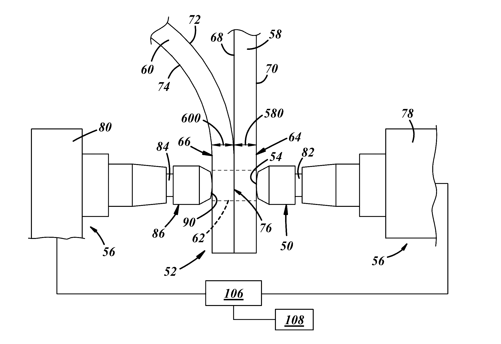
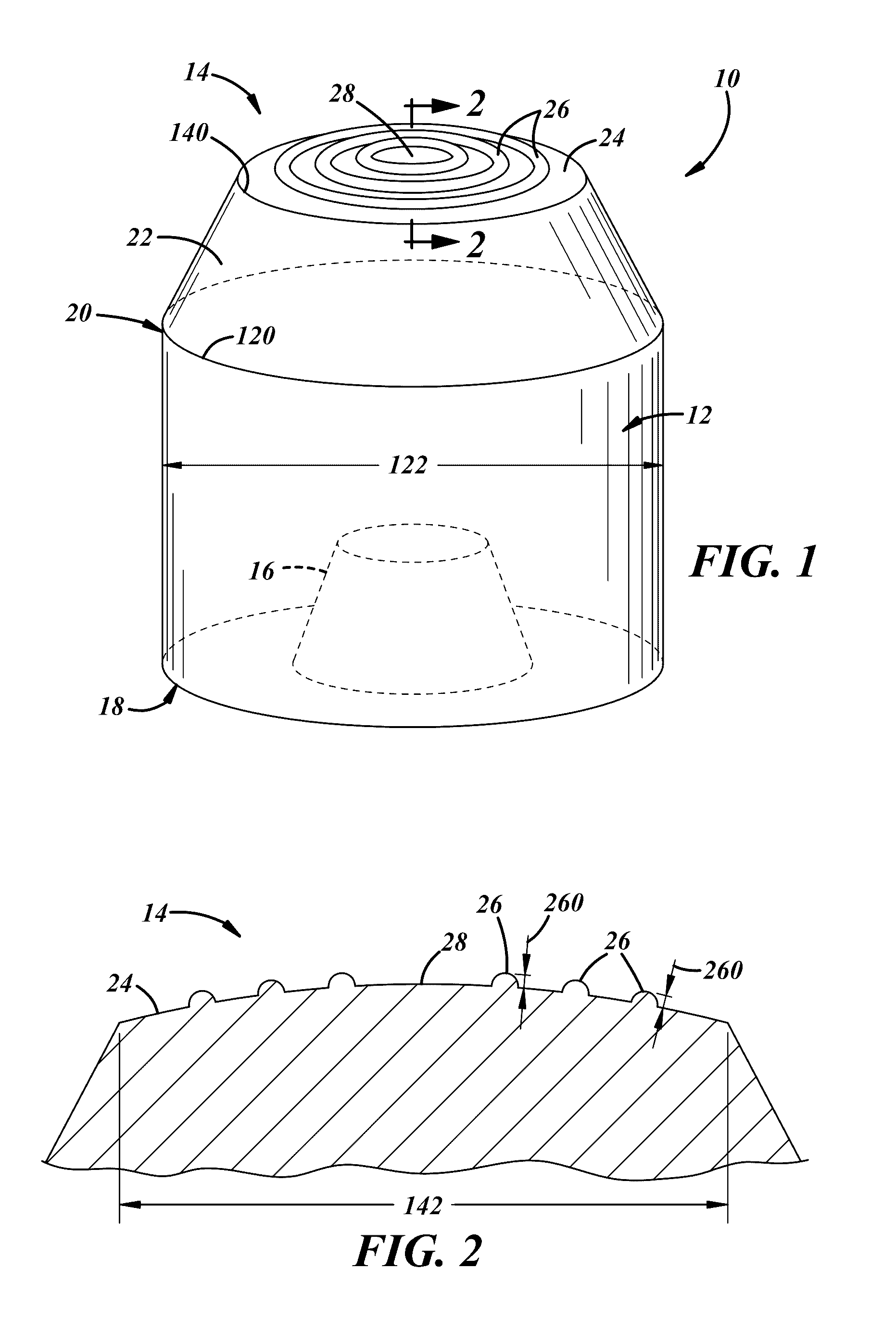
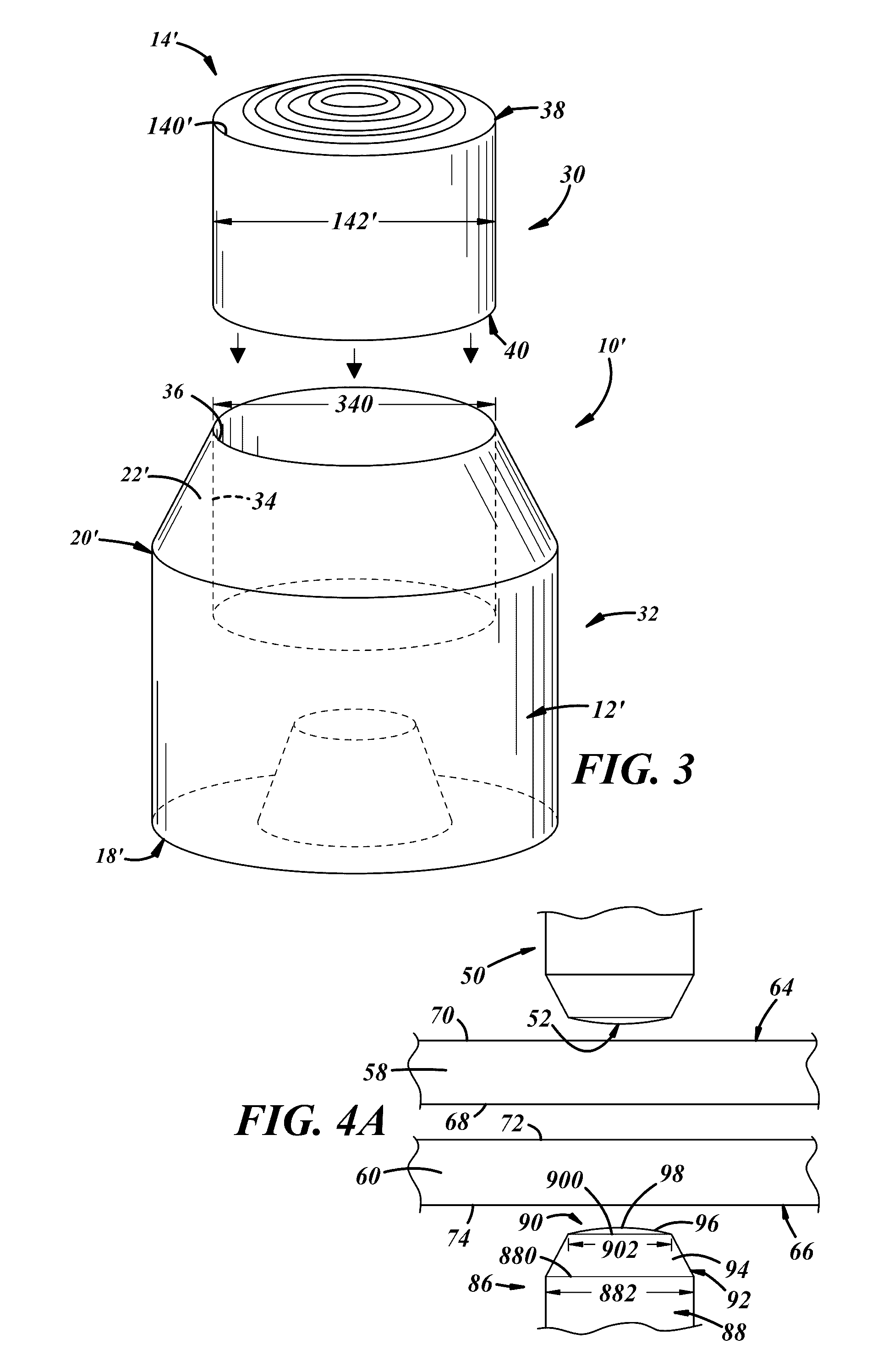
[0030]The resistive welding electrode described below includes at least a weld face—which may be smooth or include raised surface features—constructed of a refractory-based material that exhibits an electrical conductivity that is less than or equal to 65% of the electrical conductivity of commercially pure annealed copper as defined by the International Annealed Copper Standard (IACS). In other words, the refractory-based material has an electrical conductivity of less than 3.8×10⁷ S / m. Several embodiments of the resistive welding electrode are depicted in FIGS. 1-3. When used to resistance spot weld a workpiece stack-up that includes an aluminum alloy workpiece arranged in lapped contacting configuration with a steel workpiece, an example of which is shown generally in FIGS. 5-8, the resistive welding electrode is brought into contact with, and pressed against, the aluminum alloy workpiece while a second welding electrode is brought into contact with, and pressed against, the stee...


PUM

PropertyMeasurementUnit
electrical conductivityaaaaaaaaaa
diameteraaaaaaaaaa
diameteraaaaaaaaaa

Abstract

A resistive welding electrode includes at least a weld face constructed of a refractory-based material that exhibits an electrical conductivity that is less than or equal to 65% of the electrical conductivity of commercially pure annealed copper as defined by the International Annealed Copper Standard (IACS). A method of using the resistive welding electrode to resistance spot weld a workpiece stack-up that includes an aluminum alloy workpiece and steel workpiece that overlap and contact each other at a faying interface is also disclosed.

Description

CROSS-REFERENCE TO RELATED APPLICATION[0001]This application claims the benefit of U.S. provisional application No. 62 / 139,197, filed on Mar. 27, 2015, the entire contents of which are incorporated herein by reference.TECHNICAL FIELD[0002]The technical field of this disclosure relates generally to resistance spot welding and, more particularly, to resistance spot welding an aluminum alloy workpiece and a steel workpiece.BACKGROUND[0003]Resistance spot welding is a process used by a number of industries to join together two or more metal workpieces. The automotive industry, for example, often uses resistance spot welding to join together pre-fabricated metal workpieces during the manufacture of vehicle closure members (e.g., a door, hood, trunk lid, or lift gate) and vehicle body structures (e.g., body sides and cross-members), among others. A number of spot welds are typically formed along a peripheral edge of the metal workpieces or some other bonding region to ensure the part is s...

Claims


Application Information

Patent Timeline
Patent Type & Authority Applications(United States)
IPC IPC(8): B23K11/30B23K11/18B23K11/20
CPCB23K11/3009B23K11/185B23K11/20B23K35/0205B23K35/32B23K2103/20
Inventor SIGLER, DAVID R.CARLSON, BLAIR E.KARAGOULIS, MICHAEL J.KELLY, DAVID P.
Owner GM GLOBAL TECH OPERATIONS LLC
Why Eureka
Try Eureka