Integration of Swing Energy Recovery and Engine Anti-Idling Systems

a technology of electronic hydrodynamic control and engine, applied in the direction of engine starters, machines/engines, mechanical equipment, etc., can solve the problems of system less responsive to operator swing commands, fluid exiting the swing motor at the end of each swing is under a relatively high pressure, and energy associated with high-pressure fluid may be wasted

Active Publication Date: 2016-09-29
CATERPILLAR INC
View PDF7 Cites 15 Cited by
  • Summary
  • Abstract
  • Description
  • Claims
  • Application Information

AI Technical Summary

Benefits of technology

[0009]In one aspect of the present disclosure, a hydraulic control system for a machine having a power source is disclosed. The hydraulic control system may include a work tool movable through a range of motion, a pump driven by the power source to pressurize fluid, an actuator configured to receive pressurized fluid from the pump and move the work tool, and a first accumulator selectively fluidly connected to the pump and to the actuator. The hydraulic control system may further include an assist motor operatively connected to the power source, a discharge valve having a normally closed position and an open position, the discharge valve positioned to selectively fluidly connect the first accumulator to the assist motor, and a controller operatively connected to the discharge valve. The controller may be configured to detect operator input to start the power source and to cause the discharge valve to move to the open position to fluidly connect the first accumulator to the assist motor to assist in starting the power source in response to detecting the operator input to start the power source.

Problems solved by technology

One problem associated with this type of hydraulic arrangement involves efficiency.
In particular, the pressurized oil provided by the pump may slowly accelerate the work tool to its steady state swing speed, making the hydraulic system less responsive to the operator swing commands than is desirable to efficiently complete the required tasks.
Moreover, the fluid exiting the swing motor at the end of each swing is under a relatively high pressure due to deceleration of the loaded work tool.
Unless recovered, energy associated with the high-pressure fluid may be wasted.
In addition, restriction of this high-pressure fluid exiting the swing motor at the end of each swing can result in heating of the fluid, which must be accommodated with an increased cooling capacity of the machine.
Moreover, the discharge valve cannot be opened during charging portions of the excavation cycle, so excess kinetic energy may be wasted or lost once the accumulator is fully charged.
Another efficiency issue associated with these types of hydraulic arrangements arises during times when the hydraulic machine is idle and yet still operational.
During this time, the engine of the machine may still be turned on (often at high speeds) and needlessly consuming fuel.
However, restarting the engine can be harsh on the machine's electrical circuit and cause delays in the work cycle of the machine.
In some applications, this overuse of the electrical circuit could cause premature wear and / or failure.
In addition, it may take some time for the engine to be turned on and ramp up to required speeds.
This time delay could result in loss of productivity and / or become a nuisance for the operator.
Such systems may not be highly efficient because the main pump works at high pressure and low flow rate, and hardware redundancy occurs where separate accumulate charge and discharge valves are provided for the anti-idling system.

Method used


Image

  • Integration of Swing Energy Recovery and Engine Anti-Idling Systems
  • Integration of Swing Energy Recovery and Engine Anti-Idling Systems
  • Integration of Swing Energy Recovery and Engine Anti-Idling Systems

Examples


Embodiment Construction

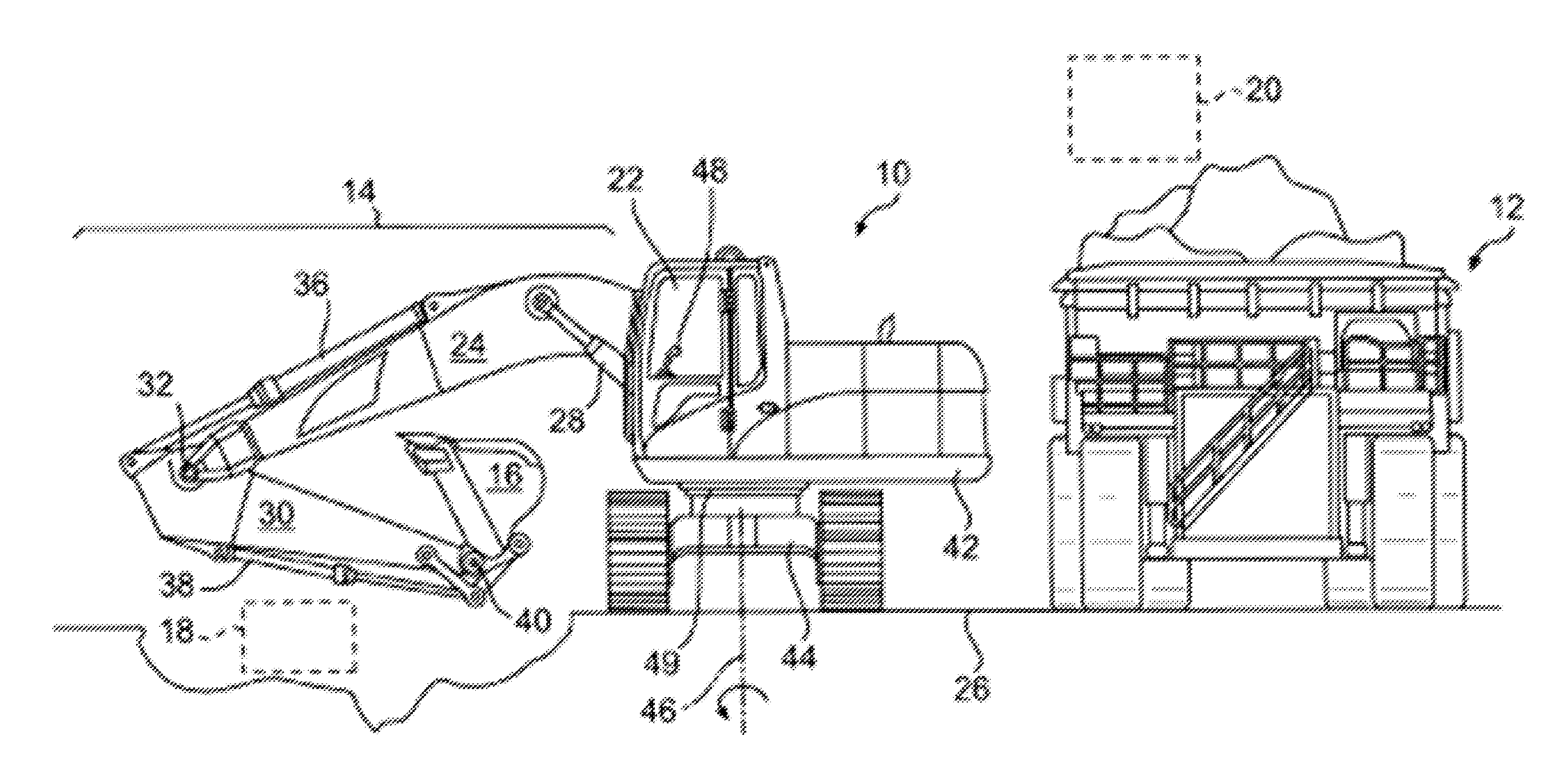
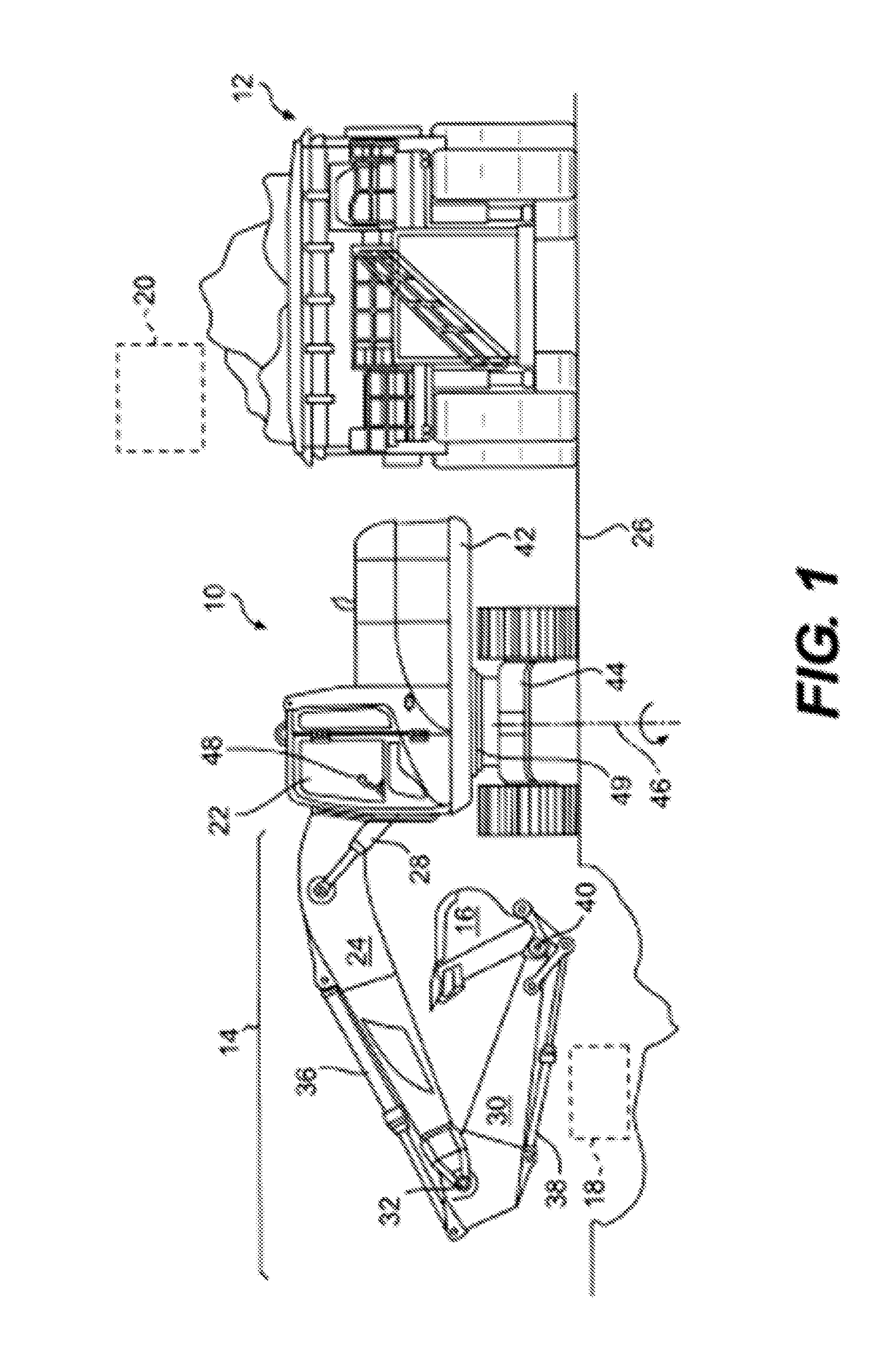
[0018]FIG. 1 illustrates an exemplary machine 10 having multiple systems and components that cooperate to excavate, carry, scoop, or otherwise move material, and, in one example, load material onto a nearby haul vehicle 12 (or another dump / unload location of material). In the depicted example, the machine 10 is a hydraulic excavator. It is contemplated, however, that the machine 10 could alternatively embody another excavation, loading, or material handling machine, such as a wheel loader, a backhoe, a front shovel, a dragline excavator, a crane, or another similar machine. The machine 10 may include, among other things, a hydraulic system 14 configured to move a work tool 16, such as a bucket in the depicted example, through a range of motion between a dig location 18 within a trench or at a pile, and a dump location 20, for example over the haul vehicle 12. The machine 10 may also include an operator station 22 for manual control of the hydraulic system 14. It is contemplated that...


PUM


Abstract

Engine anti-idling and restart may be implemented in a machine having a power source, a movable work tool, a pump driven by the power source, an actuator receiving fluid from the pump and moving the work tool, a high-pressure fluid reservoir, and an assist motor operatively connected to the power source. Engine restart may include detecting operator input to start the power source, and fluidly connecting the fluid reservoir to the assist motor to assist in starting the power source in response to detecting the operator input. Prior to shutting down the power source during anti-idling, fluid from the pump may be input to the assist motor, pressurized and communicated to the high-pressure fluid reservoir in response to determining that idle condition exists and a reservoir charge pressure is less than a reservoir minimum restart pressure needed to restart the power source.

Description

TECHNICAL FIELD[0001]The present disclosure relates generally to electro-hydraulic control systems and, more particularly, to electro-hydraulic control systems for recovering and reusing swing kinetic energy and boom potential energy.BACKGROUND[0002]Hydraulic machines such as excavators, dozers, loaders, backhoes, motor graders, and other types of heavy equipment use one or more hydraulic actuators to accomplish a variety of tasks. These actuators are fluidly connected to an engine-driven pump of the machine that provides pressurized fluid to chambers within the actuators. As the pressurized fluid moves into or through the chambers, the pressure of the fluid acts on hydraulic surfaces of the chambers to affect movement of the actuators and a connected work tool.[0003]Swing-type excavation machines, for example hydraulic excavators and front shovels, require significant hydraulic pressure and flow to transfer material from a dig location to a dump location. These machines direct the ...

Claims


Application Information

Patent Timeline
Patent Type & Authority Applications(United States)
IPC IPC(8): F15B1/033F15B21/14F15B13/02E02F9/22
CPCF15B1/033E02F9/2217F15B13/02F15B21/14E02F9/2221F02N7/00F15B1/024F15B2211/20523F15B2211/20569F15B2211/212F15B2211/6309F15B2211/6313F15B2211/6346F15B2211/6651F15B2211/7058F15B2211/851F15B2211/88F02N2200/10E02F9/2242E02F9/2296
Inventor SHANG, TONGLINMA, PENGFEICHEN, DAYAOPETERSON, JEREMYMORRIS, EMILY ANNE
Owner CATERPILLAR INC
Why Eureka
Try Eureka