High-frequency circuit and transmission and reception circuit using high-frequency circuit

a high-frequency circuit and high-frequency circuit technology, applied in transmission, multiple-port network, electrical equipment, etc., can solve the problems of insufficient impedance matching between variable bpf and circulator, increase in transmission loss, and inability to perform impedance matching. to achieve the effect of suppressing degradation of reception characteristics and reliable impedance matching

Active Publication Date: 2016-09-29
MURATA MFG CO LTD
View PDF5 Cites 7 Cited by
  • Summary
  • Abstract
  • Description
  • Claims
  • Application Information

AI Technical Summary

Benefits of technology

[0018]In the above configuration, two high-frequency circuits are connected to the first high-frequency device, and each of the high-frequency circuits is the above-described high-frequency circuit. The first high-frequency device is a wide-band circulator. An antenna is connected to the first high-frequency device. One of the high-frequency circuits functions as a transmitter circuit, and the other of the high-frequency circuits functions as a receiver circuit. Accordingly, even if the antenna is shared between the transmitter circuit and the receiver circuit, it is possible to reliably perform impedance matching in accordance with the variation in the operating frequency of the variable filter and to suppress degradation in reception characteristics.

Problems solved by technology

However, there has been a problem as follows.
Accordingly, impedance matching cannot be performed sufficiently between the variable BPF and a circulator.
Accordingly, impedance matching cannot be performed sufficiently, which may result in generation of various characteristics (e.g., increase in transmission loss and degradation in reception sensitivity).
That is, there has been a problem as follows.
Even if a high-frequency device that can be adapted to various operating frequencies is realized, it is not possible to embody a high-frequency circuit adapted to various operating frequencies unless a matching circuit that connects the high-frequency device and another device to each other is adapted to various operating frequencies.

Method used


Image

  • High-frequency circuit and transmission and reception circuit using high-frequency circuit
  • High-frequency circuit and transmission and reception circuit using high-frequency circuit
  • High-frequency circuit and transmission and reception circuit using high-frequency circuit

Examples


first embodiment

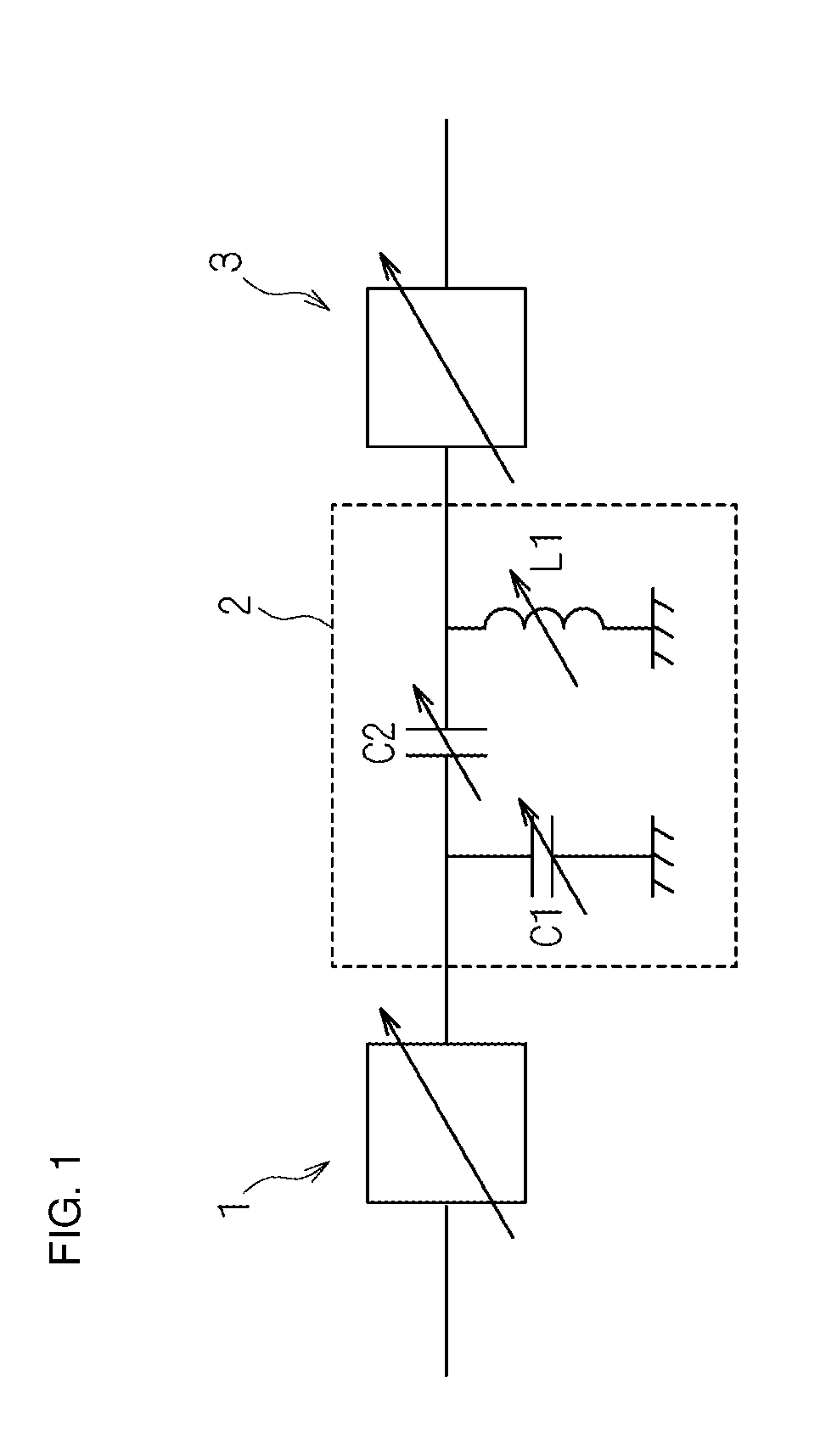
[0031]FIG. 1 is a schematic diagram illustrating a configuration of a high-frequency circuit according to a first embodiment of the present disclosure. As illustrated in FIG. 1, a matching circuit 2 capable of adjusting the input / output impedances of a first high-frequency device 1 and a second high-frequency device 3 whose operating frequencies can be set in a wide frequency band is connected in the high-frequency circuit according to the first embodiment.

[0032]In the first embodiment, it is assumed that the first high-frequency device 1 and the second high-frequency device 3 operate in a plurality of frequency bands defined by the 3GPP standard, that is, a wide frequency band.

[0033]As a high-frequency device whose operating frequency can be set in a wide frequency band, there is a variable element, typically a variable filter whose operating frequency can be set to a predetermined frequency by setting the element value of a variable device included in the variable filter to a pred...

second embodiment

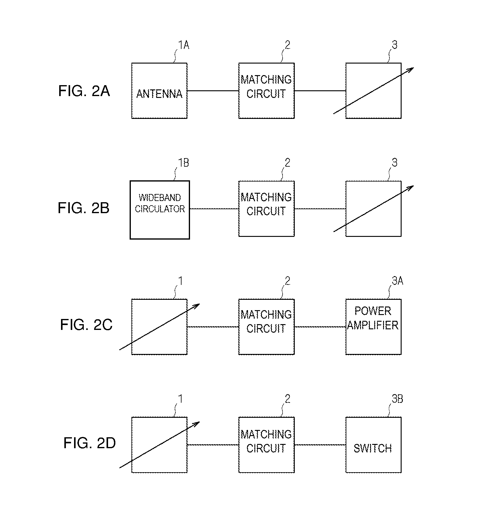
[0048]FIG. 6 is a schematic diagram illustrating a configuration of a high-frequency circuit according to a second embodiment of the present disclosure. As illustrated in FIG. 6, in the high-frequency circuit according to the second embodiment, a wide-band circulator (or isolator) 1B and a variable filter 3C are respectively employed as the first high-frequency device 1 and the second high-frequency device 3. In the same manner as in the first embodiment, the matching circuit 2 is connected between the wide-band circulator 1B and the variable filter 3C. A receiver circuit that receives signals from the antenna 1A is formed in such a manner that the antenna 1A and a low-noise amplifier 3D are respectively connected to the wide-band circulator 1B and the variable filter 3C.

[0049]In the case where the operating frequency varies owing to the operation of the variable filter 3C handling a change in the frequency of a reception signal, it is possible to adjust the input / output impedances ...

third embodiment

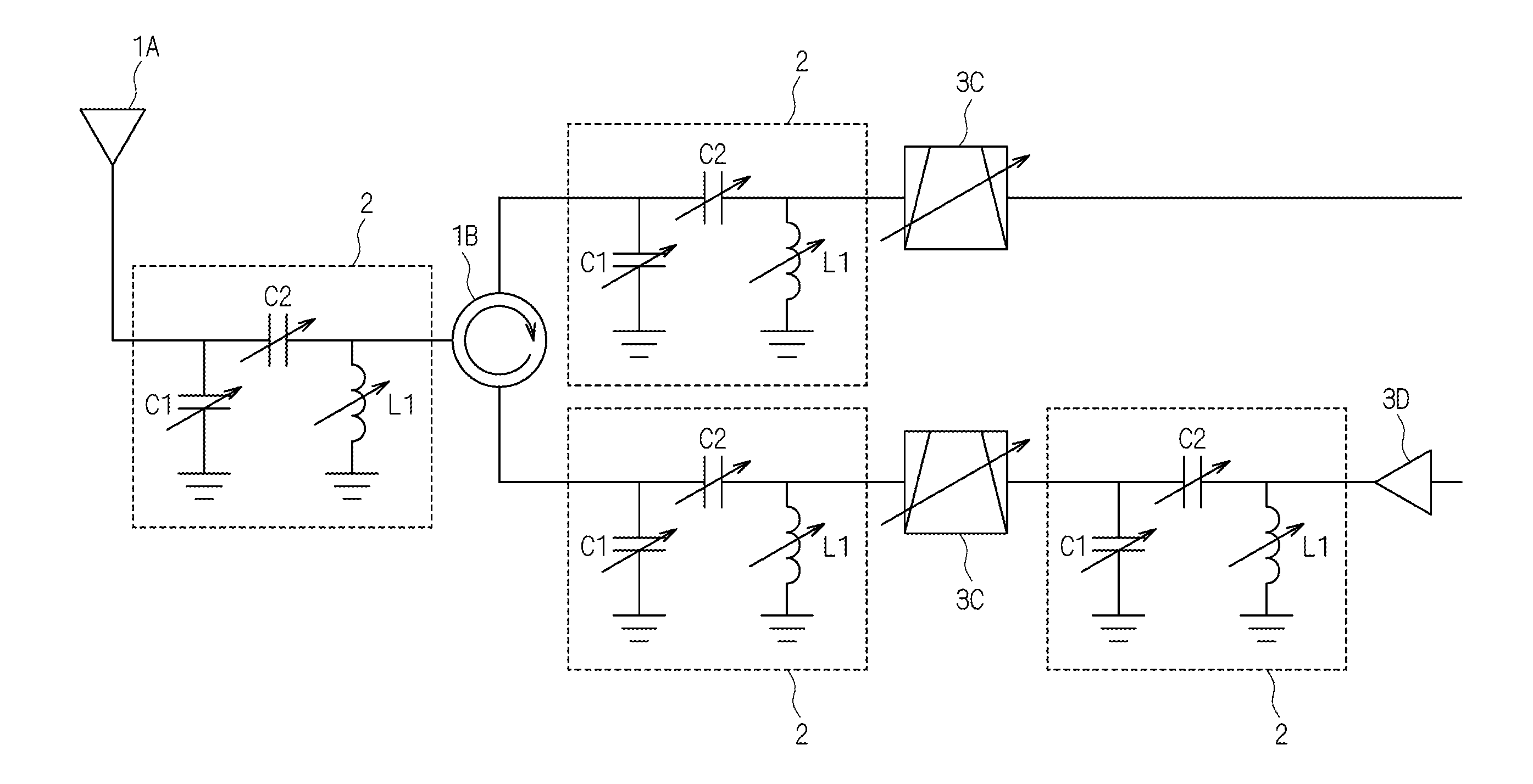
[0054]FIG. 8 is a schematic diagram illustrating a configuration of a transmission and reception circuit according to a third embodiment of the present disclosure. As illustrated in FIG. 8, in the transmission and reception circuit according to the third embodiment, two high-frequency circuits, which are the high-frequency circuits described in the first embodiment and the second embodiment, are connected to each other with the wide-band circulator 1B, which is the first high-frequency device 1, interposed therebetween.

[0055]That is, one of the high-frequency circuits functions as a transmitter circuit, and the other of the high-frequency circuits functions as a receiver circuit. The transmitter circuit and the receiver circuit share the antenna 1A with the wide-band circulator 1B interposed therebetween, thereby being capable of transmitting and receiving signals.

[0056]Each of two matching circuits 2 is connected between the wide-band circulator 1B and a corresponding one of variab...


PUM


Abstract

The present disclosure provides a high-frequency circuit including a matching circuit capable of adjusting the input/output impedance of a high-frequency device to an optimal value, even if the high-frequency device includes a circuit element whose input/output impedance varies upon the variation in the operating frequency, and provides a transmission and reception circuit including the high-frequency circuit. The high-frequency circuit includes a first high-frequency device, a second high-frequency device electrically connected to the first high-frequency device, and a matching circuit connected between the first high-frequency device 1 and the second high-frequency device. At least one of the first high-frequency device 1 and the second high-frequency device includes a variable device and has a changeable operating frequency. The matching circuit includes at least one variable device capable of performing impedance matching in accordance with operating frequencies of the first high-frequency device and the second high-frequency device.

Description

BACKGROUNDTechnical Field[0001]The present disclosure relates to a high-frequency circuit including a matching circuit capable of adjusting the input / output impedance of a high-frequency device to an optimal value even if an operating frequency varies, and relates to a transmission and reception circuit using the high-frequency circuit.[0002]In electronic components, in the case where electrical signals on a transmitter side in a transmission path have a constant power, if the output impedance of a transmitter circuit and the input impedance of a receiver circuit are made to be equal to each other, the receiver circuit obtains the maximum power. Accordingly, it is necessary to make those impedances equal to each other (hereinafter referred to as “to perform impedance matching”) for efficient transmission.[0003]In the case where impedance matching is not performed sufficiently, the receiver circuit cannot obtain the desired maximum output. In a high-frequency circuit, in particular, ...

Claims


Application Information

Patent Timeline
Patent Type & Authority Applications(United States)
IPC IPC(8): H04B1/04H03H7/12H03H7/38H04B1/18
CPCH04B1/0458H03H7/38H03H7/12H04B1/18H03H7/40H03H7/463
Inventor WADA, TAKAYA
Owner MURATA MFG CO LTD
Why Eureka
Try Eureka