
Vertical tunneling finfet

a technology of vertical tunneling and finfet, which is applied in the direction of diodes, semiconductor devices, electrical apparatus, etc., can solve the problems of small leakage current that is highly sensitive to the applied voltage, the dimension has shrunk below, and the conventional silicon device geometries and materials have experienced difficulty in maintaining switching speeds without incurring failures,

Active Publication Date: 2016-10-06
STMICROELECTRONICS SRL
View PDF10 Cites 88 Cited by
  • Summary
  • Abstract
  • Description
  • Claims
  • Application Information

AI Technical Summary

Benefits of technology

The tunneling FinFET can be made using standard CMOS processes and is low-powered, which allows it to provide a high current density compared to traditional planar devices. This patent describes a technical solution for creating efficient and high-current density semiconductor devices using advanced technology.

Problems solved by technology

As device dimensions have shrunk below 100 nm, however, conventional silicon device geometries and materials have experienced difficulty maintaining switching speeds without incurring failures such as, for example, leaking current from the device into the semiconductor substrate.
However, in reality, in the sub-threshold regime, there exists a small leakage current that is highly sensitive to the applied voltage.
Over time, the leakage current drains charge from the power supply, e.g., a mobile phone battery or a computer battery, thus necessitating more frequent recharging.

Method used


Image

  • Vertical tunneling finfet
  • Vertical tunneling finfet
  • Vertical tunneling finfet

Examples


Embodiment Construction

[0020]In the following description, certain specific details are set forth in order to provide a thorough understanding of various aspects of the disclosed subject matter. However, the disclosed subject matter may be practiced without these specific details. In some instances, well-known structures and methods of semiconductor processing comprising embodiments of the subject matter disclosed herein have not been described in detail to avoid obscuring the descriptions of other aspects of the present disclosure.

[0021]Unless the context requires otherwise, throughout the specification and claims that follow, the word “comprise” and variations thereof, such as “comprises” and “comprising” are to be construed in an open, inclusive sense, that is, as “including, but not limited to.”

[0022]Reference throughout the specification to “one embodiment” or “an embodiment” means that a particular feature, structure, or characteristic described in connection with the embodiment is included in at le...


PUM


Abstract

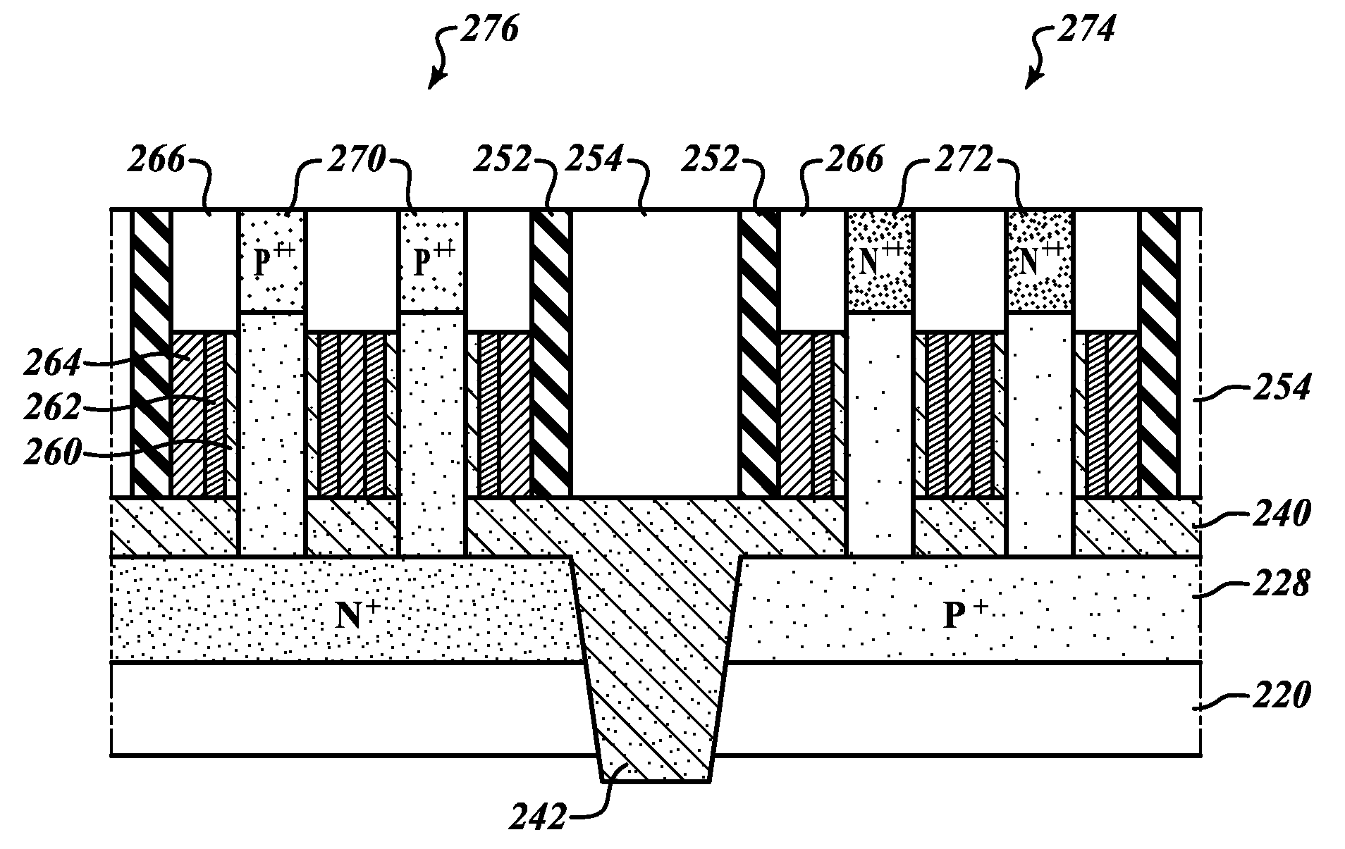
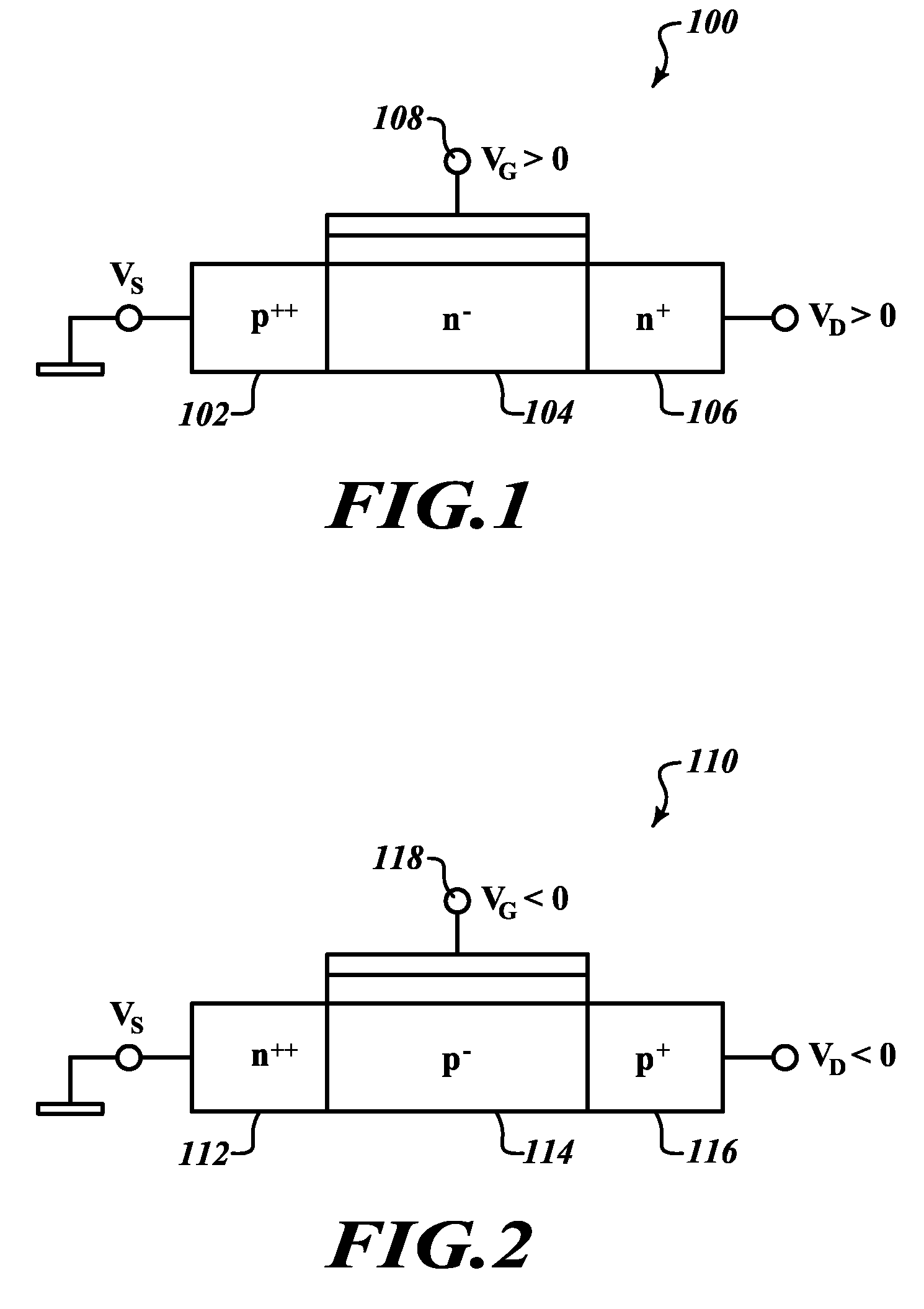
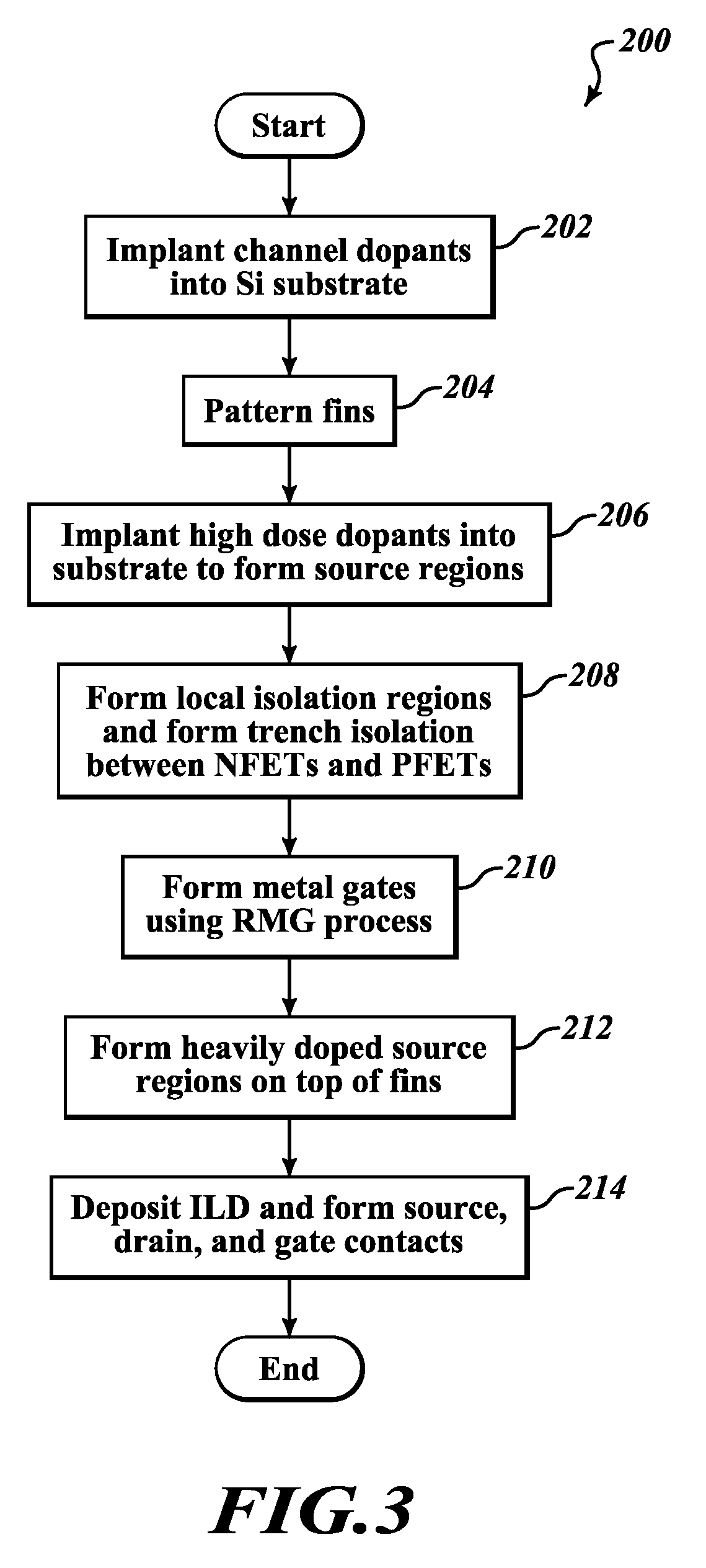
A tunneling transistor is implemented in silicon, using a FinFET device architecture. The tunneling FinFET has a non-planar, vertical, structure that extends out from the surface of a doped drain formed in a silicon substrate. The vertical structure includes a lightly doped fin defined by a subtractive etch process, and a heavily-doped source formed on top of the fin by epitaxial growth. The drain and channel have similar polarity, which is opposite that of the source. A gate abuts the channel region, capacitively controlling current flow through the channel from opposite sides. Source, drain, and gate terminals are all electrically accessible via front side contacts formed after completion of the device. Fabrication of the tunneling FinFET is compatible with conventional CMOS manufacturing processes, including replacement metal gate and self-aligned contact processes. Low-power operation allows the tunneling FinFET to provide a high current density compared with conventional planar devices.

Description

BACKGROUND[0001]1. Technical Field[0002]The present disclosure generally relates to various geometries for FinFET devices built on a silicon substrate and, in particular, to FinFETs suitable for low-power applications.[0003]2. Description of the Related Art[0004]Conventional integrated circuits incorporate planar field effect transistors (FETs) in which current flows through a semiconducting channel between a source and a drain, in response to a voltage applied to a control gate. The semiconductor industry strives to obey Moore's law, which holds that each successive generation of integrated circuit devices shrinks to half its size and operates twice as fast. As device dimensions have shrunk below 100 nm, however, conventional silicon device geometries and materials have experienced difficulty maintaining switching speeds without incurring failures such as, for example, leaking current from the device into the semiconductor substrate. Several new technologies have emerged that allow...

Claims


Application Information

Patent Timeline
Patent Type & Authority Applications(United States)
IPC IPC(8): H01L29/78H01L29/267H01L29/165H01L29/66H01L29/16
CPCH01L29/7827H01L29/66666H01L29/267H01L29/165H01L29/1608H01L29/7391H01L29/785H01L29/4958H01L29/517H01L21/823885H01L27/092H01L21/823487H01L29/66356
Inventor LIU, QINGZHANG, JOHN H.
Owner STMICROELECTRONICS SRL
Learn More