Ferromagnetic-particle manufacturing apparatus

a technology of ferromagnetic particles and manufacturing equipment, which is applied in the direction of electric/magnetic/electromagnetic heating, nickel oxides/hydroxides, and nickel compounds, etc., can solve the problems of small variation in composition and dimension of ferromagnetic particles generated, unlikely to vary, and reduce the generation efficiency of ferromagnetic particles, etc., to achieve efficient manufacturing and solve the effect of ferromagnetic particle generation

Inactive Publication Date: 2016-10-13
DAI ICHI HIGH FREQUENCY
View PDF5 Cites 3 Cited by
  • Summary
  • Abstract
  • Description
  • Claims
  • Application Information

AI Technical Summary

Benefits of technology

[0006]In view of the above disadvantages, the present invention has been made for efficiently solve the same. The object of the pres...

Problems solved by technology

Thus, the reaction liquid is unlikely to vary in temperature and a mixed condition of the reaction liquid is unlikely to be non-uniform, so that variation of the generated ferromagnetic particles in composition and ...

Method used


Image

  • Ferromagnetic-particle manufacturing apparatus
  • Ferromagnetic-particle manufacturing apparatus
  • Ferromagnetic-particle manufacturing apparatus

Examples


first embodiment

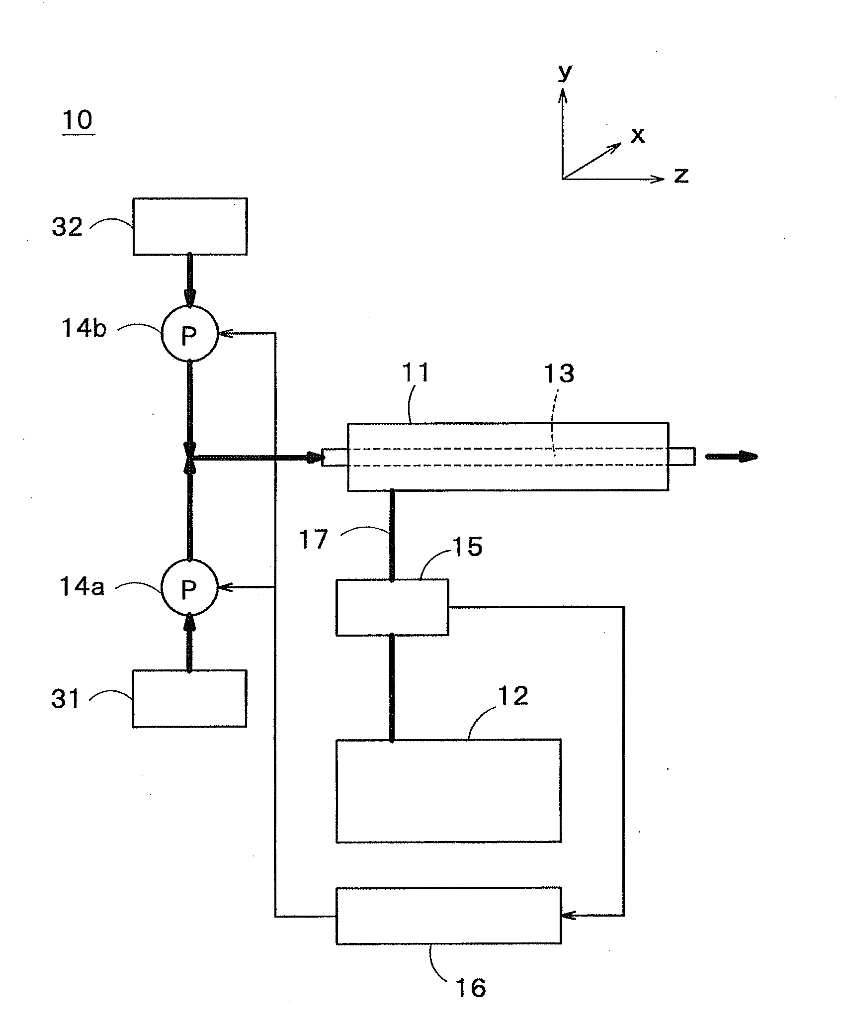
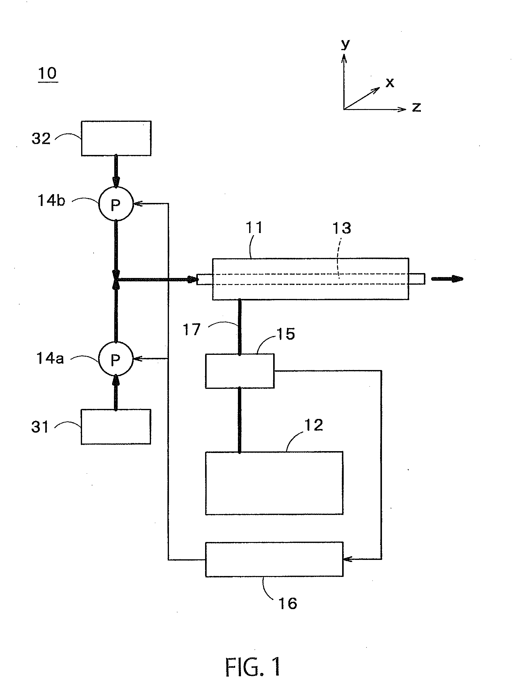
[0025]FIG. 1 is a schematic structural view showing a ferromagnetic-particle manufacturing apparatus in the present invention.

[0026]As shown in FIG. 1, a ferromagnetic-particle manufacturing apparatus 10 in this embodiment includes: a single mode cavity 11 that resonates with a microwave of a predetermined wavelength; a microwave oscillator 12 electrically connected to the single mode cavity 11 and configured to introduce the microwave of a predetermined wavelength into the single mode cavity 11; a pipe 13 disposed to pass through the inside of the single mode cavity 11, the pipe 13 being formed of a dielectric material; and pumps 14a and 14b configured to introduce, from one end of the pipe 13, an alkaline reaction liquid in which metal ions of a ferromagnetic metal and hydroxide ions are dissolved.

[0027]The single mode cavity 11 is a hollow container made of a conductive wall such as a metal, and is also referred to as cavity resonator. The single mode cavity 11 is configured to r...

second embodiment

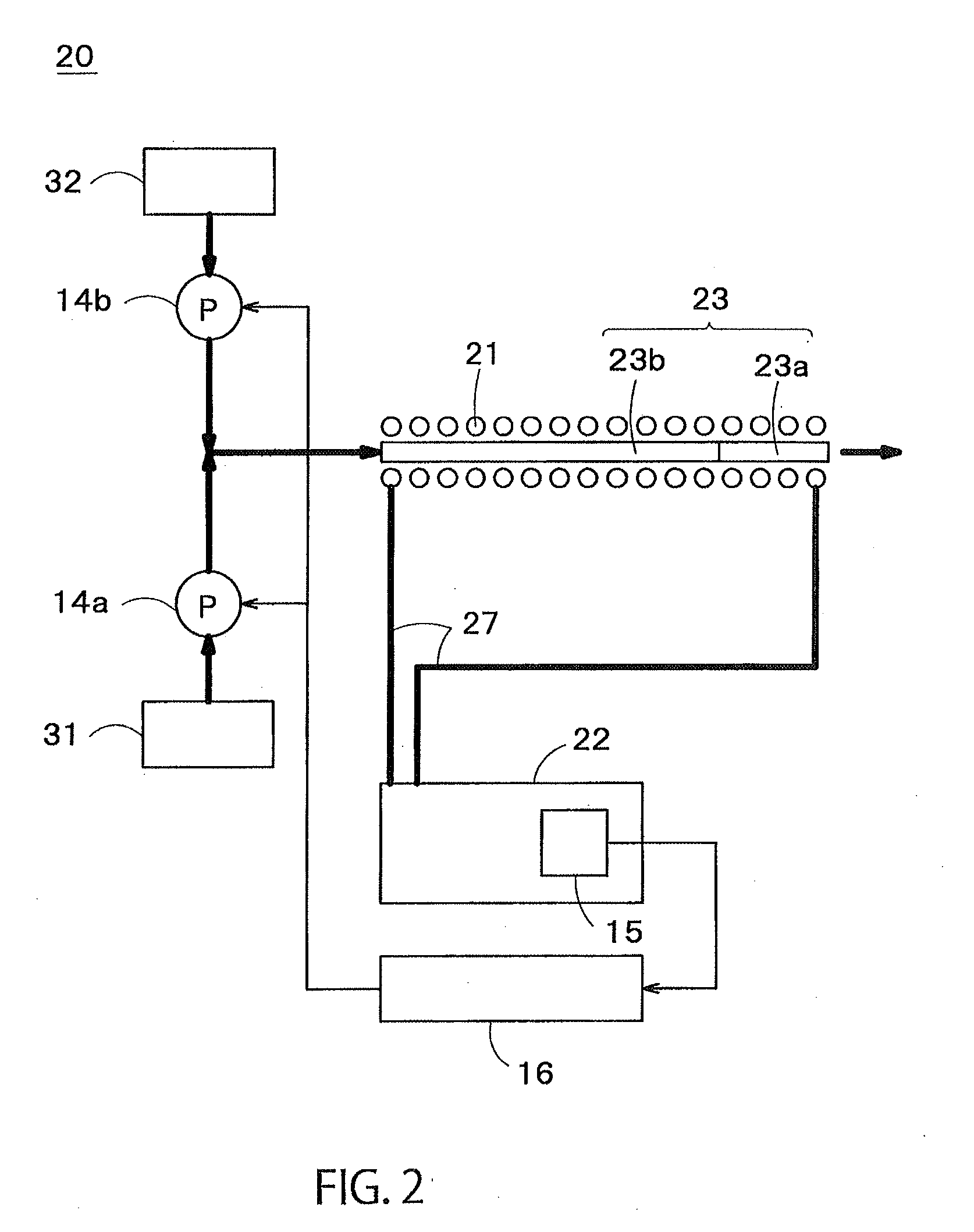
[0056]FIG. 2 is a schematic structural view showing a ferromagnetic-particle manufacturing apparatus in the present invention.

[0057]As shown in FIG. 2, in place of the single mode cavity 11, the microwave oscillator 12 and the pipe 13 formed of a dielectric material of the ferromagnetic-particle manufacturing apparatus 10 in the first embodiment, a ferromagnetic-particle manufacturing apparatus 20 in the second embodiment includes: an induction heating coil 21; a radiofrequency power source 22 electrically connected to the induction heating coil 21 and configured to form an alternating field inside the induction heating coil 21; and a pipe 23 disposed to pass through the inside of the induction heating coil 21. At least a partial area 23a of the pipe 23 in an axial direction thereof is formed of a dielectric material. An area 23b, which is nearer to one end of the pipe 2 than the area 23a formed of a dielectric material, is formed of a conductive material.

[0058]The induction heating...


PUM

PropertyMeasurementUnit
Lengthaaaaaaaaaa
Lengthaaaaaaaaaa
Diameteraaaaaaaaaa

Abstract

A ferromagnetic-particle manufacturing apparatus includes: a single mode cavity that resonates with a microwave of a predetermined wavelength; a microwave oscillator electrically connected to the single mode cavity and configured to introduce the microwave of a predetermined wavelength into the single mode cavity; a pipe disposed to pass through an inside of the single mode cavity, the pipe being formed of a dielectric material; a pump configured to introduce, from one end of the pipe, an alkaline reaction liquid containing metal ions of a ferromagnetic metal; an impedance measuring device configured to measure an impedance of the single mode cavity; and a pump-flowrate deciding unit configured to decide, based on a measurement result of the impedance measuring device, a pump flowrate by which the impedance of the single mode cavity becomes a predetermined value or more; wherein the pump is configured to introduce the reaction liquid at the pump flowrate decided by the pump-flowrate deciding unit; and wherein ferromagnetic particles are generated by reacting the reaction liquid.

Description

TECHNICAL FIELD[0001]The present invention relates to a ferromagnetic-particle manufacturing apparatus.BACKGROUND ART[0002]Due to magnetic properties, ferromagnetic particles (nanoparticles) are recently used as active pharmaceutical ingredients for a magnetic resonance imaging method (MRI), a drug delivery system (DDS), a local hyperthermia treatment and so on.[0003]JP2006-28032A discloses a method of generating magnetite particles, which are one type of such ferromagnetic particles, by using a coprecipitation reaction. Specifically in this method, a predetermined amount of ferrous chloride (FeCl2) solution and a predetermined amount of ferric chloride (FeCl3) solution are put into a reaction container. While the solutions are heated and stirred in the reaction container, sodium hydroxide (NaOH) solution is added thereto. Thus, a coprecipitation reaction between ferrous ions (Fe2+) and ferric ions (Fe3+) occurs so that magnetite (Fe3O4) particles are generated.[0004]In such a conve...

Claims


Application Information

Patent Timeline
IPC IPC(8): B01J19/12B01J19/06C01G49/08H01F1/20C01G53/00H05B6/80H05B6/10B22F9/24B01J19/02C01G53/04B22F1/05
CPCB01J19/126B22F2301/35B01J19/06C01G49/08C01G53/04C01G53/40H05B6/806H05B6/108B22F9/24H01F1/20B01J2219/0204B01J2219/0871B01J2219/0877B01J2219/1215B01J2219/1245C01P2006/42B22F2009/245B22F2301/15B01J19/02C01G49/0018H05B2214/04B22F2999/00C22C2202/02B22F1/05B22F3/003
Inventor HIRAYAMA, KOTAROTANOUE, SHOTA
Owner DAI ICHI HIGH FREQUENCY
Why Eureka
Try Eureka