Fluid manifold

a manifold and fluid technology, applied in the field of manifolds, can solve the problems of increasing fluid noise and heat generation in the hydraulic system, affecting the operation of the manifold, and reducing the efficiency of the manifold, so as to reduce the manufacturing time and cost, reduce the weight, and reduce the material use

Inactive Publication Date: 2016-10-13
EMERALD2 SYST L L C
View PDF2 Cites 4 Cited by
  • Summary
  • Abstract
  • Description
  • Claims
  • Application Information

AI Technical Summary

Benefits of technology

[0015]Another feature is that material not required to produce a functional fluid manifold can be omitted from the additive manufacturing process. This results in a reduced material use and a reduction of manufacturing time and costs.
[0016]Another feature is that material not required to produce a functional fluid manifold can be omitted from the additive manufacturing process. This results in a fluid manifold reduced weight.
[0017]Another feature is that the fluid passages are fabricated during the additive manufacturing with radius curves in place of angular cross drillings allowing for the removal of the cross drilling pilot drilling This allows for a reduction of fluid manifold physical size.
[0018]Another feature includes using alternating materials during the additive manufacturing process to allow for lined fluid passages, thereby allowing fluids of different corrosiveness to be present in the same fluid manifold.
[0019]Another feature includes using alternating materials during the additive manufacturing process to allow a corrosion resistant coating to encase the fluid manifold, thereby reducing the manufacturing time and cost by eliminating the need for a plating operation.

Problems solved by technology

The structural design and subtractive manufacturing of a fluid manifold is a cause of a large proportion of the total energy loss, increased fluid noise and heat generation in a hydraulic system.
This loss is primarily due to the fluid manifold's internal flow passages.
Limitations in machining processes often dictate and restrict the layout and manufacture of the hydraulic integrated circuit.
Also, internal manifold chambers must meet these fabrication limitations causing sudden cavity enlargements and or sudden contractions.
Unfortunately, these component interconnections produce excessive fluid vortices and eddy formations that result in excessive energy losses and fluid noise.
However, cost limitations and access to the internal portions of the manifold result in fluid manifolds that are heavier, larger in physical size, energy inefficient result in the waste of manufacturing materials.

Method used


Image

  • Fluid manifold
  • Fluid manifold
  • Fluid manifold

Examples


Embodiment Construction

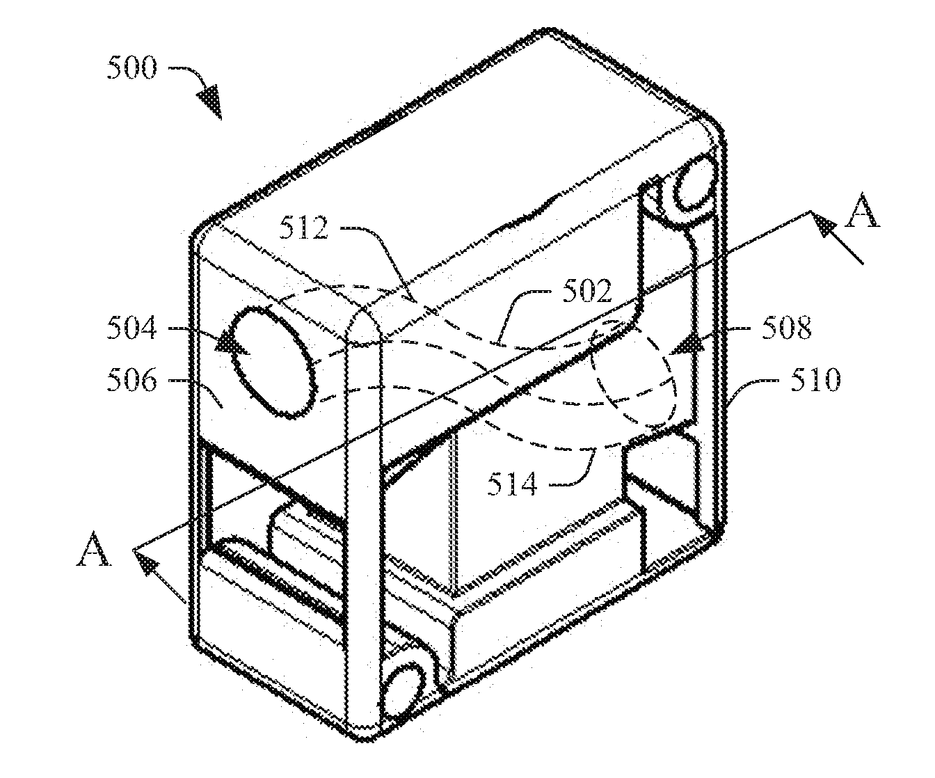
[0036]The following describes a manifold configured with a chamber and a passage through which a material (e.g., a liquid, a gas, a solid, etc.) is distributed, gathered, etc., and / or one or more other manifolds. The manifold, which is constructed through an additive manufacturing technology such as 3-D printing, has reduced weight, reduced physical size, improved system energy efficiency, reduced use of manufacturing materials and / or reduced cost, relative to a configuration fabricated via subtractive and / or other manufacturing process, which might leave undesired and / or unneeded material in and / or on the manifold.

[0037]As utilized herein, additive manufacturing includes a process of making a three-dimensional solid object of virtually any shape (e.g., square, rectangular, “L”, irregular, etc.) from a digital model. One approach utilizes powdered material dispersed across the manufacturing machine's base plate in layers, allowing for the required detail resolution, and fused togeth...


PUM


Abstract

A fluid manifold includes a block with a first aperture, a second aperture, and a curved fluid passage fabricated, via an additive manufacturing process, through the block between the first aperture and the second aperture. The curved fluid passage surrounds a cavity and includes a non-zero radius of curvature. A fluid manifold includes a volume of material and a fluid passage fabricated, via an additive manufacturing process, through the volume of material. The fluid passage includes a first passive element having a first diameter, a second passive element having a second diameter, and an orifice having a third diameter. The orifice is located between the first and second passive elements. The first and second diameters are smaller than the third diameter. A fluid manifold having a single block of material with a curved passage fabricated through the single block of material is prepared by an additive manufacturing process.

Description

CROSS-REFERENCE TO RELATED APPLICATIONS[0001]This application claims the benefit of U.S. Provisional Application Ser. No. 62 / 144,403, filed Apr. 8, 2015, and entitled “METHOD FOR THE MANUFACTURE OF FLUID MANIFOLDS UTILIZING ADDITIVE MANUFACTURING TECHNOLOGY,” which is hereby incorporated by reference in its entirety.TECHNICAL FIELD[0002]The following generally relates to a manifold and more particularly to a fluid manifold.BACKGROUND OF THE INVENTION[0003]The hydraulic integrated circuit is one of the foundations of modern hydraulic technology and is indispensable across a wide range of applications and has experienced explosive growth in use over the last few decades. Hydraulic integrated circuits have widespread use in mobile equipment because their compact and modular designs simplify installation and troubleshooting; reduce leakage through reduced number of interconnections, and offer substantially lower manufacturing and installation costs. The hydraulic integrated circuit find...

Claims


Application Information

Patent Timeline
Patent Type & Authority Applications(United States)
IPC IPC(8): F15D1/02
CPCF15D1/025F15B13/0814F15B13/0871B33Y80/00F16K27/003
Inventor TAYLOR, WILLIAM P.
Owner EMERALD2 SYST L L C
Why Eureka
Try Eureka