

Far-Infrared Imaging Device and Far-Infrared Imaging Method
a technology of infrared imaging and imaging method, which is applied in the direction of optical radiation measurement, instruments, spectrometry/spectrophotometry/monochromators, etc., can solve the problems of difficult handling and limited research use of electromagnetic waves, and achieve the effect of performing imaging at a high speed
- Summary
- Abstract
- Description
- Claims
- Application Information
AI Technical Summary
Benefits of technology
Problems solved by technology
Method used
Image

Examples
example 1
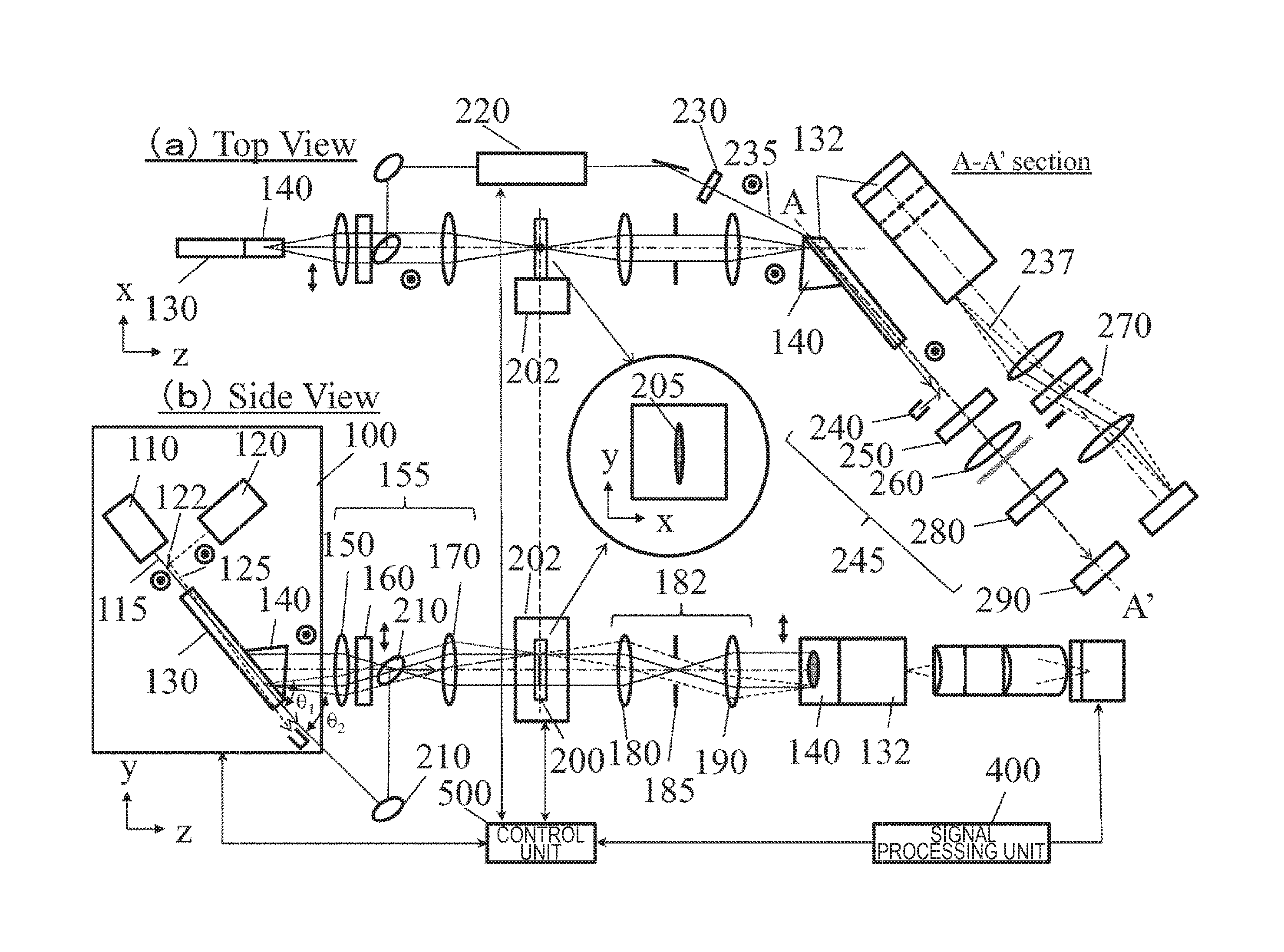
[0027]FIG. 1 illustrates an example of the whole configuration of an imaging apparatus in Example 1. FIG. I illustrates a configuration example of an apparatus for imaging an image of a specimen 200 by using light transmitted through the specimen 200. This apparatus includes a wavelength-tunable far-infrared light source 100, an illumination optical system 155, a stage 202, a far-infrared light imaging optical system 182, a non-linear optical crystal 132 for detection, a detection optical system 245, a light detector 290, a pump light irradiation optical system 220, a control unit 500, and a signal processing unit 400.
[0028]As the wavelength-tunable far-infrared light source 100, there is used a far-infrared light source for generating far-infrared light due to difference frequency generation or parametric generation by causing two kinds of laser beams having different wavelengths to enter a non-linear optical crystal. For example, when MgO:LiNbO3 is used as a non-linear optical cry...
example 2
[0048]FIG. 6 illustrates a configuration example of an imaging apparatus in Example 2. In this configuration, imaging is performed by using reflected light of the specimen 200. The directions of the optical path from the wavelength-tunable far-infrared light source 100 to the illumination optical system 155 and the optical path from the far-infrared imaging optical system 182 and thereafter are changed at the surface of the specimen 200, far-infrared light is caused to be obliquely incident on the specimen 200 and reflected light thereof is detected. With this, it is possible to measure a specimen having low transmittance and measure a spectroscopic property of a surface of the specimen. When a mechanism system capable of changing incident angles of an illumination system and an imaging optical system is constructed, incident angle dependency of the spectroscopic property can be also measured.
example 3
[0049]FIG. 7 illustrates a configuration example of an imaging apparatus in Example 3. In this configuration, imaging is performed by causing far-infrared light to be vertically incident on the specimen 200 and using reflected light thereof When the wavelength-tunable far-infrared light source 100 to the illumination optical system 155 and the far-infrared imaging optical system 182 and thereafter are overlapped by a beam splitter 206 around the surface of the specimen 200, far-infrared light is caused to be vertically incident on the specimen 200 and reflected light thereof is detected. In the case where a polarization beam splitter is used as the beam splitter 206, it is possible to omit the polarization rotation optical element 160. Further, it is also possible to form a system for polarizing and separating incident light and reflected light by using a polarization beam splitter as the beam splitter 206 and providing a quarter-wave plate therebehind. With this, even in the case W...
PUM
 Abstract
Description
Claims
Application Information