
Ultrasound imaging device and imaging method thereof

an ultrasonic imaging and ultrasonic technology, applied in the field of medical technology, can solve the problems of image reconstruction error, difficult to fix breast, and inability to scan the peripheral mammary gland

Active Publication Date: 2016-10-20
SHENZHEN MINDRAY BIO MEDICAL ELECTRONICS CO LTD
View PDF8 Cites 10 Cited by
  • Summary
  • Abstract
  • Description
  • Claims
  • Application Information

AI Technical Summary

Benefits of technology

The patent describes a system for analyzing ultrasound signals to determine the quality of a scan. The system uses a driving mechanism to perform a second scanning of a target object to obtain additional ultrasound signals. These signals are then analyzed by a signal processor to generate a second ultrasound image. The technical effect of this patent is to provide a more precise and accurate way to scan target objects using ultrasound technology.

Problems solved by technology

An advantage of the supine position is that the breast has no deformation during the scanning process, and a disadvantage is that the peripheral mammary gland cannot be scanned.
A disadvantage of the prone position is that the breast is not easy to be fixed due to the flowing water, and the breast deformation can affect image reconstruction error during the scanning process.
Another disadvantage is that the upper surface and lower surface of the water bag may form a reverberation, which leads to artifacts.
In addition, the water immersion method has disadvantages, such as the thickness of the liquid (water) between the ultrasound probe and the tissue may affect image quality, region of interest may not be in the physical focus area, and bubbles produced by the rotating ultrasound probe in the water may affect the image quality.
Some disadvantages of the splint type scanning may include: a scanning position is different with an operation position, the peripheral mammary gland cannot be scanned, the patient feels uncomfortable, and it is not suitable for patients with small breasts.
However, the current press down type automated mammary gland scanning method has certain disadvantages.
For example, as the reconstruction is performed after mechanical scanning, if some area has pool contact with the body tissue and is separated by air, a shadow will be generated and thus will seriously affect the quality of the images.
Because the scanning time is usually long, whether the contact situation is desirable cannot be known in advance, so the success rate of data collecting will be affected.

Method used


Image

  • Ultrasound imaging device and imaging method thereof
  • Ultrasound imaging device and imaging method thereof
  • Ultrasound imaging device and imaging method thereof

Examples


first embodiment

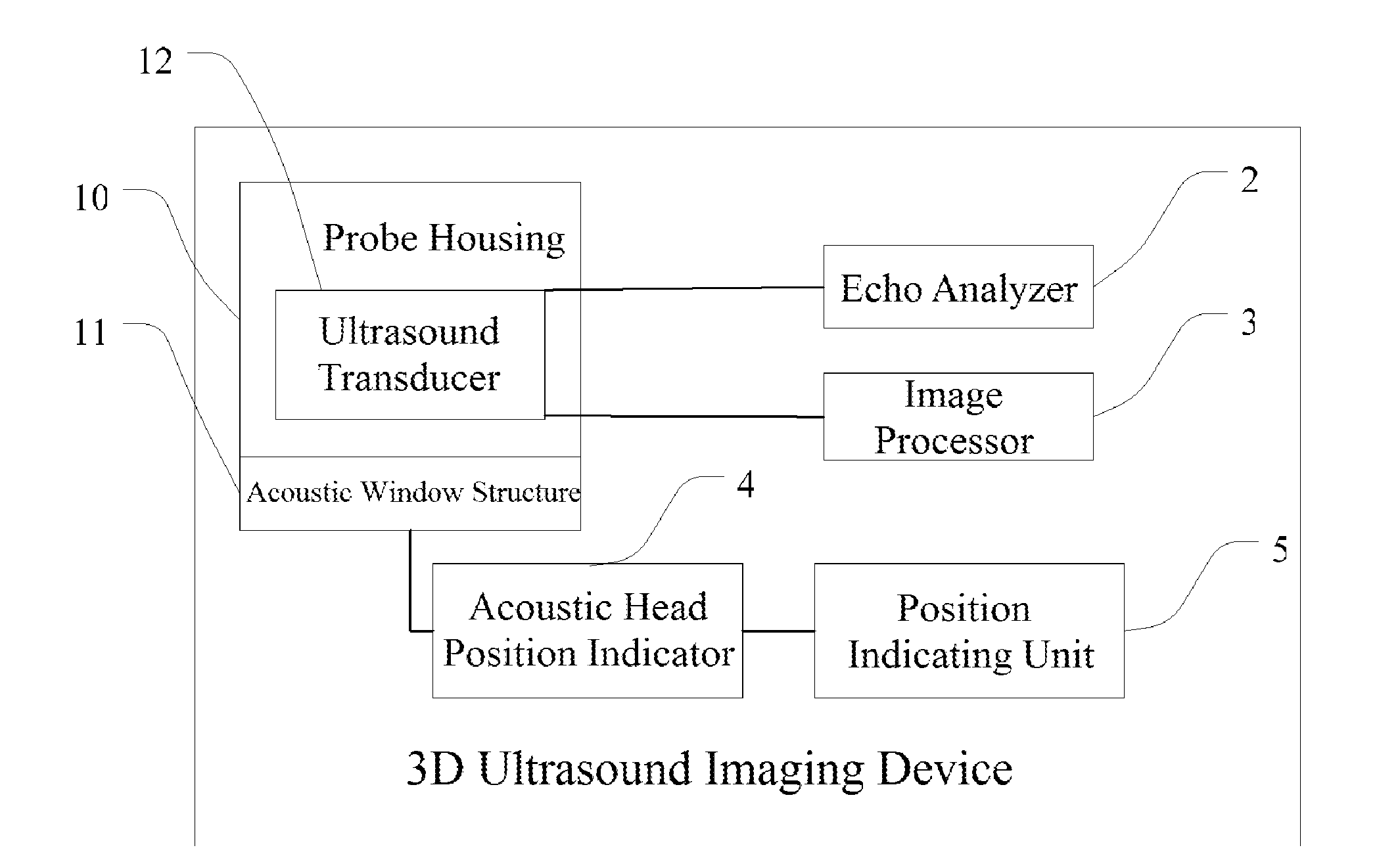
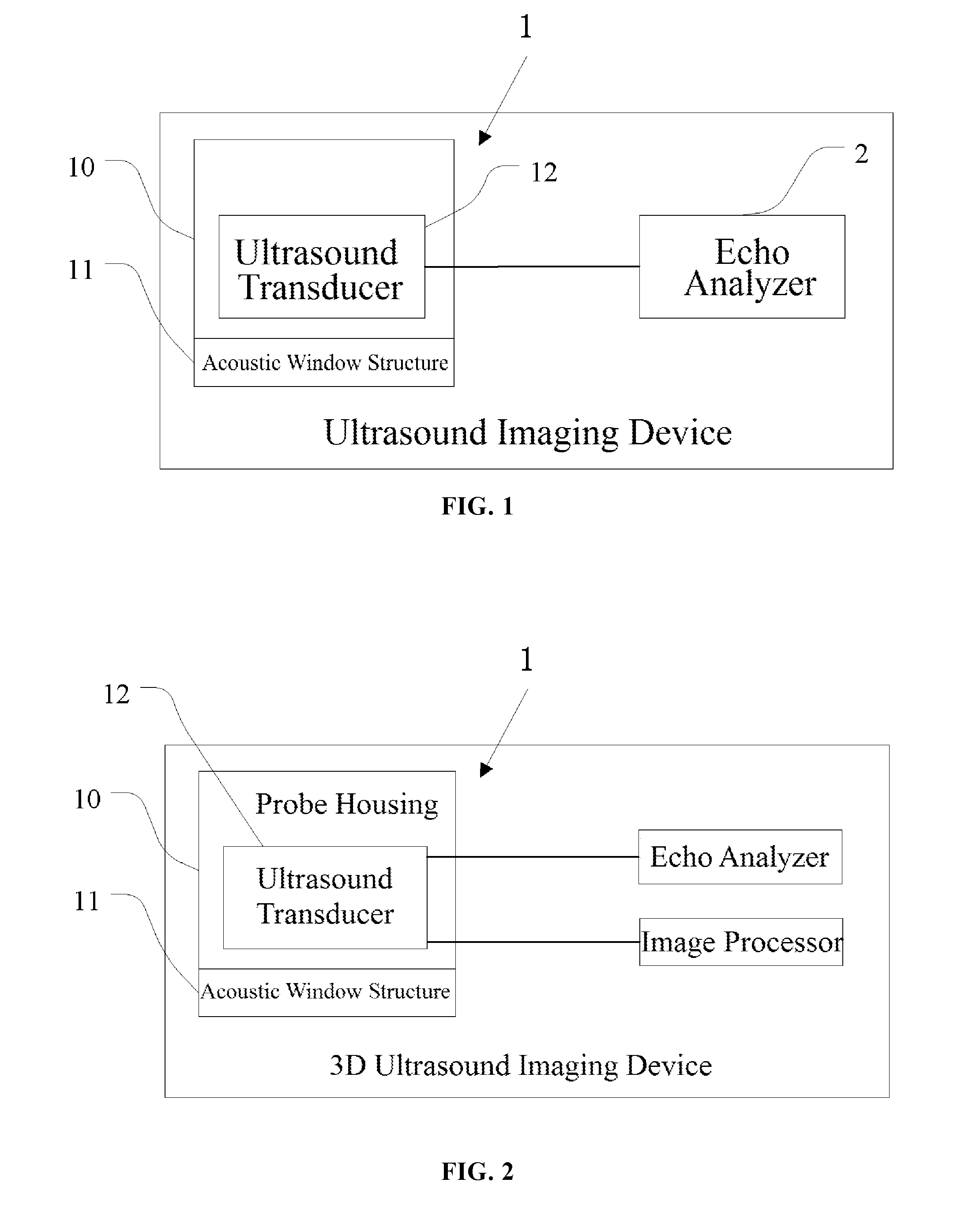
[0129]Referring to FIG. 1, it is a schematic diagram illustrating a structure of a 3D ultrasound imaging device according to the present disclosure.

[0130]The 3D ultrasound imaging device of the first embodiment includes an ultrasound probe assembly 1 and a signal processor, and the signal processor may include an echo analyzer 2.

[0131]The ultrasound probe assembly 1 may include:

a. a probe housing 10;

b. an acoustic window 11, which is located under and abutted against the probe housing 10 to form a sealed chamber, wherein the sealed chamber is filled with coupling oil, and surface of the acoustic window 11 contacts with the breast of the body to be examined; and

[0132]an ultrasound transducer 12 which includes an acoustic head and a vertical shaft, wherein the acoustic head is immersed in the coupling oil in the sealed chamber, and the acoustic head moves back and forth repetitively at a first speed to pre-scan the breast of the body to be examined through the surface of the acoustic ...

second embodiment

[0137]Referring to FIG. 2, it is a schematic diagram illustrating a structure of a 3D ultrasound imaging device according to the present disclosure.

[0138]Comparing to the first embodiment, the device according to the second embodiment further includes:

[0139]an image processor configured to process the ultrasound signals acquired by moving the ultrasound transducer back and forth repetitively at the second speed in the sealed chamber, and analyze the ultrasound signals collected at a depth and reconstruct a 3D coronal plane image.

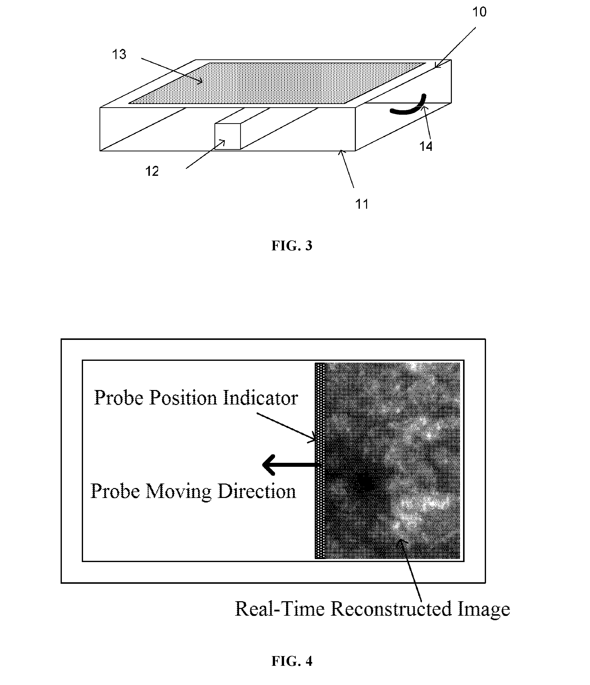
[0140]Referring to FIG. 3, it is a schematic diagram illustrating a structure of an ultrasound probe assembly according to a first embodiment of a 3D ultrasound imaging device according to an embodiment of the present disclosure.

third embodiment

[0141]The third embodiment will focus on a detailed structure of the ultrasound probe assembly 1 of the 3D ultrasound imaging device. The ultrasound probe assembly 1 may include:

[0142]a probe housing 10;

[0143]an acoustic window 11, which is located under and abutted against the probe housing 10 to form a sealed chamber, wherein the sealed chamber is filled with coupling oil, and surface of the acoustic window 11 contacts with the breast of the body to be examined; and

[0144]an ultrasound transducer 12 which includes an acoustic head and an vertical shaft, wherein the acoustic head is immersed in the coupling oil in the sealed chamber, and the acoustic head moves back and forth repetitively at a first speed to pre-scan the breast of the body to be examined through the surface of the acoustic window 11, to obtain initial ultrasound signals; the ultrasound transducer 12 also can move back and forth repetitively at a second speed to perform a re-scanning to obtain ultrasound signals.

[014...


PUM


Abstract

A 3D ultrasound imaging device including an ultrasound probe assembly and echo analyzer. The ultrasound probe assembly includes a housing and an acoustic window abutted against the housing to form a sealed chamber, wherein the surface of the acoustic window contacts with the breast of the human body to be examined; an ultrasound transducer moves at a first speed back and forth within the sealed chamber and performs high-speed pre-scanning through the acoustic window to obtain initial ultrasound signals; the echo analyzer analyzes the initial ultrasound signals to determine a quality of a ultrasound image acquired by the high speed pre-scanning; and the ultrasound transducer then moves at a second speed to perform another scan to acquire new ultrasound signals. A 3D ultrasound imaging method is also disclosed.

Description

TECHNICAL FIELD[0001]The present disclosure relates to the medical technology field and particularly to an ultrasound imaging device and method thereof.BACKGROUND[0002]Ultrasound is one of the most important imaging tools in breast screening. The ultrasound examination has no radiation, it is convenient to use, and the cost is low. The ultrasound examination is beneficial and does not cause damage to people with large glands or dense glands and young women, especially near the pectorals.[0003]The technology of automatic breast scanning has developed in recent years. It scans the breast tissue using a mechanical scanning device and then constructs models, thereby allowing doctors to observe the breast tissue in coronal planes and obtain results normal ultrasound imaging cannot achieve.[0004]The technical idea of full breast scanning includes a water immersion method and direct contact method. The water immersion method further includes supine type and prone type. With the water immer...

Claims


Application Information

Patent Timeline
Patent Type & Authority Applications(United States)
IPC IPC(8): A61B8/08A61B8/13A61B8/00A61B8/14
CPCA61B8/0825A61B8/5269A61B8/4245A61B8/13A61B8/4461A61B8/14A61B8/483A61B8/5246A61B8/4427A61B8/54A61B8/52A61B8/523A61B8/5215A61B8/5292G01N35/00594G01N35/021G01N2035/0413
Inventor SHI, ZHIWEIZHU, ZIYANZHU, LEI
Owner SHENZHEN MINDRAY BIO MEDICAL ELECTRONICS CO LTD
Learn More