
Optical particle counter

Active Publication Date: 2016-10-20
ALPHASENSE LTD
View PDF11 Cites 10 Cited by
  • Summary
  • Abstract
  • Description
  • Claims
  • Application Information

AI Technical Summary

Benefits of technology

This patent describes a method that allows for the detection and measurement of particles using scattered radiation. The method uses a beam of radiation that is focused on a specific area, and the intensity of the radiation is measured when a particle passes through the focused area. The intensity of the radiation is proportional to the size of the particle, and by measuring the time it takes for the radiation to be scattered by the particle, the velocity of the particle can also be measured. By measuring both the intensity and the time of flight, the method allows for more accurate measurements of particle size and velocity. The method also uses a beam of limited depth, which increases the likelihood of detecting a particle without interference from multiple particles. Overall, this method provides a more reliable and accurate way to measure the size and velocity of particles.

Problems solved by technology

On some occasions, two or more particles may pass through the particle detection zone, which can interfere with accurate measurement, but the dimensions of the apparatus are typically configured to minimise the frequency of this occurrence.

Method used


Image

  • Optical particle counter
  • Optical particle counter
  • Optical particle counter

Examples


first example

rticle Concentration for Particle Velocity

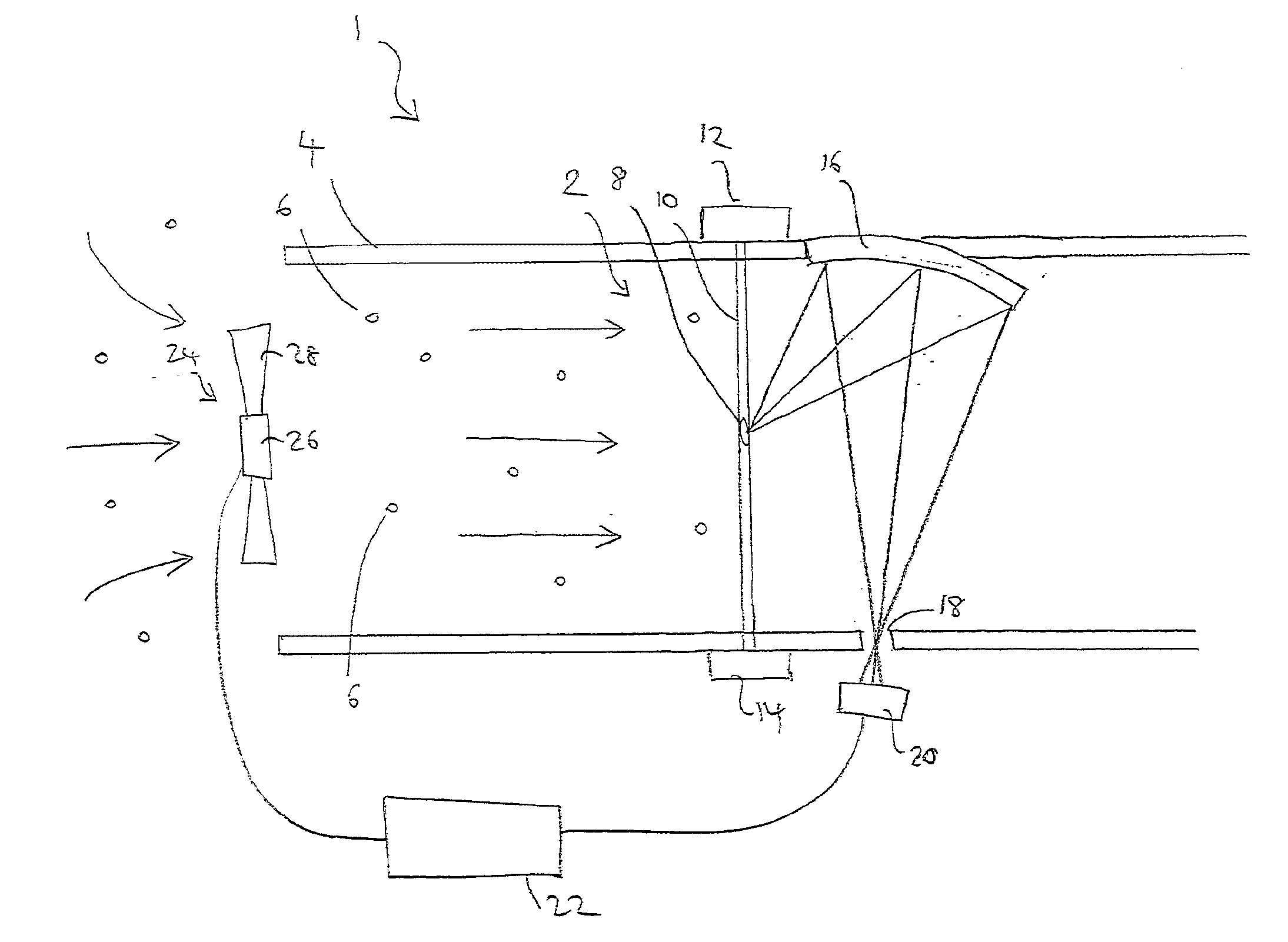
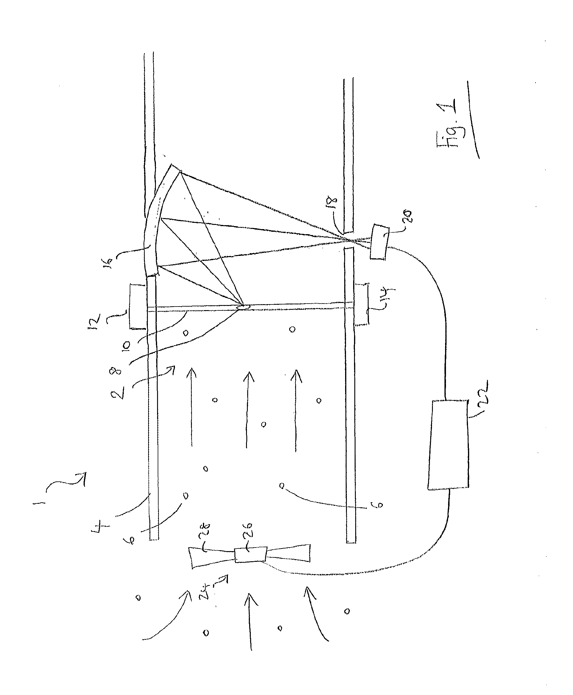
[0041]With reference to FIG. 1, an optical particle counter 1 has a scattering chamber 2, in this example defined by a tube 4 through which an air sample flows in use, bearing particles 6 to be detected. The scattering chamber includes a particle detection zone 8. The optical particle counter counts and determines the size of particles which transit the particle detection zone. A laser beam 10, functioning as the beam of radiation, is generated in use by laser 12 and extends through the scattering chamber to a beam dump 14. A parabolic reflector 16 directs light from the laser beam which is scattered by particles in the particle detection zone through an aperture 18 to a photodetector 20 (the detector, for example a photodiode) which outputs a measured light intensity signal to a processing circuit 22. One skilled in the art will appreciate that the processing circuit may be implemented by a microprocessor or microcontroller executing a comp...


PUM


Abstract

An optical particle counter determines the velocity of particles passing through a particle detection zone, and thereby the velocity of gas flow, from both the measured time of flight of discrete particles and also the size of intensity peaks of scattered light. This is used to determine particle concentration and may be used to control an optional fan.

Description

FIELD OF THE INVENTION[0001]The present invention relates to the field of optical particle counters which employ optical scattering to detect fine particulates in air (or potentially another gas). In particular, the invention relates to optical particle counters in which particles are detected individually from light scattered as they pass through a relatively shallow light beam in order to measure the concentration of particles of a particular size range, or ranges, in an air sample.BACKGROUND TO THE INVENTION[0002]Issues concerning the invention will now be discussed with reference to the example application of detecting particles in air. The same approach may be used to detect particles in other gases.[0003]Optical particle counters are known which detect the passage of particles through a beam of light (typically from a laser). Typically, a narrow column of air is passed through a light beam and the column of air is sufficiently narrow that the volume within which particles are ...

Claims


Application Information

Patent Timeline
IPC IPC(8): G01N21/47G01N21/85G01N15/14
CPCG01N21/4738G01N15/14G01N2021/8578G01N2015/1486G01N21/85G01N15/0205G01N15/1459G01N2015/0038G01N2015/1027
Inventor KAYE, PAUL HENRYHIRST, EDWIN
Owner ALPHASENSE LTD
Learn More