Automotive sensor active temperature control and temperature fault monitoring

a technology of active temperature control and automotive sensor, which is applied in the direction of temperature measurement of moving solids, instruments, mechanical equipment, etc., can solve the problems of not providing a means of actively monitoring the temperature of not providing a means of actively cooling the wheel speed sensor, etc., to reduce the future probability of measurable degraded performance, reduce the damage to the electronic automotive sensor and the measurement inaccuracy

Inactive Publication Date: 2016-10-20
DEXTER AXLE CO
View PDF10 Cites 2 Cited by
  • Summary
  • Abstract
  • Description
  • Claims
  • Application Information

AI Technical Summary

Benefits of technology

[0016]The present invention is a system to monitor the environmental temperature of automotive or industrial sensors and a means of actively heating or cooling sensors such that the sensor is not exposed to extreme cold or hot temperatures, which could negatively affect the operation of the sensor either temporarily or permanently. The operator is preferably informed of the future probability of measurable degraded performance of the automotive or industrial machine or thermal stress of sensors to enable the operator to adjust her operation of the machine and perform preventive maintenance to reduce the future probability of measurable degraded performance and thermal stress of sensors.
[0017]A system to monitor and control the environmental temperature of automotive sensors comprises a sensor assembly having an electronic automotive sensor an temperature sensor that are located in close proximity to one another. A system further has means of actively controlling or heating the electronic sensor according to an temperature operating range of electronic automotive sensor and a controller that uses the temperature sensor to monitor the temperature of the electronic automotive sensor and acts to control the means of actively cooling or heating the electronic

Problems solved by technology

WO2005047838) do not provide a means of actively cooling the wheel speed sensor, providing driver feedback, or detecting and predicting failures of the wheel speed sensor and brakes.
Combined hub temperature and wheel speed sensor systems that monitor wheel bearing temper

Method used


Image

  • Automotive sensor active temperature control and temperature fault monitoring
  • Automotive sensor active temperature control and temperature fault monitoring
  • Automotive sensor active temperature control and temperature fault monitoring

Examples


Embodiment Construction

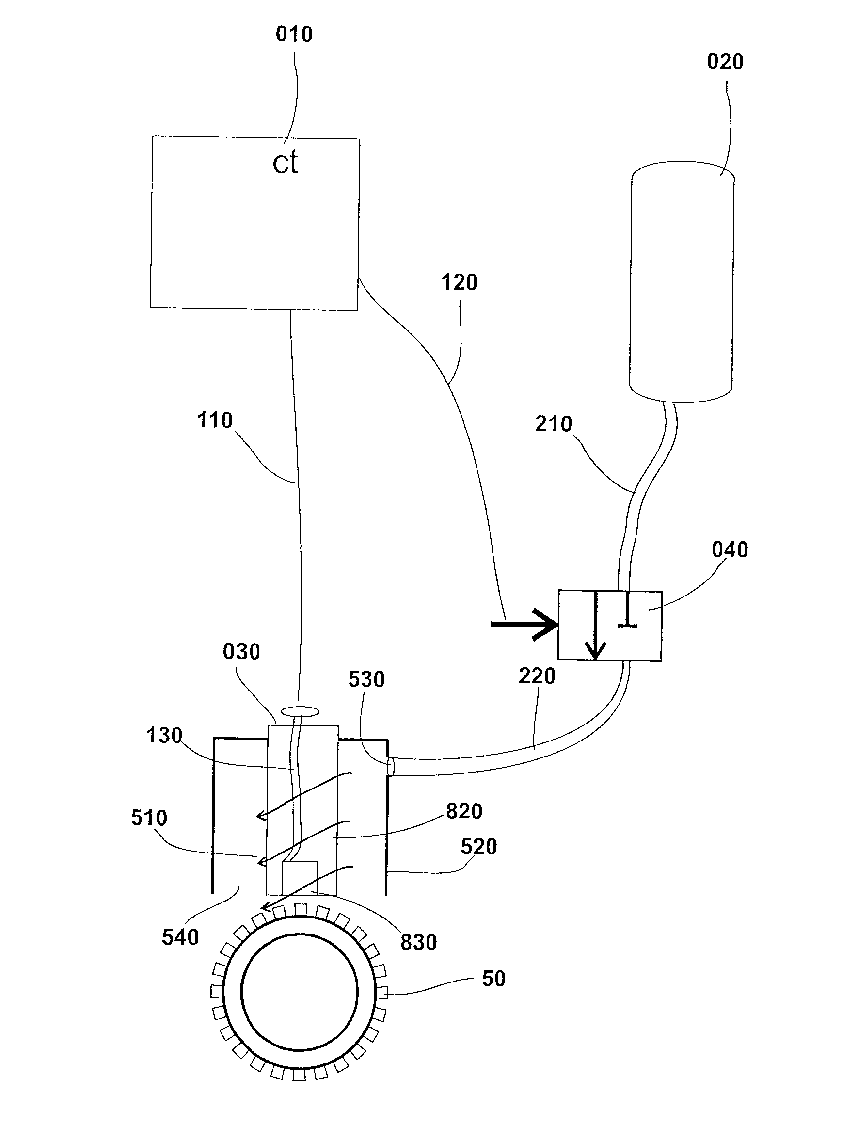
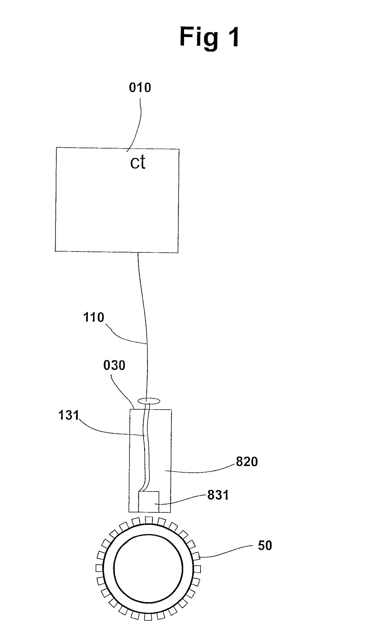
[0093]FIG. 1 is a diagrammatic view of the prior art wheel speed sensor assembly 030 with the wheel speed sensor controller 010. The internal wheel speed signal wires 131 connect the wheel speed sensor 831 to the external signal wires 110. The external signal wires 110 connect the wheel speed sensor assembly 030 to the wheel speed sensor controller 010. The controller 010 is preferably a programmable controller and still more preferably one or more of a computer processor, a programmable gate array and an application specific integrated circuit or any combination thereof. The internal wheel speed signal wires 131 are protected from the environment by electrical insulation 820. The magnetic wheel speed sensor 831 is located at the tip of the wheel speed sensor assembly 030 so that it is in close proximity to the magnetic encoder ring 050. The wheel speed sensor 831 is in close proximity to a magnetic encoder ring 050 as required to provide a magnetic field strength sufficient for rel...


PUM


Abstract

The present invention has a controller (010) to monitor the environmental temperature of automotive or industrial sensor (830) and a means of actively heating (651) or cooling (520) sensors such that the sensor (830) is not exposed to extreme cold or hot temperatures, which could negatively affect the operation of the sensor (830) either temporarily or permanently. The operator (901) is informed (356) of the future probability of measurable degraded performance of the automotive or industrial machine or thermal stress of sensors to enable the operator (901) to adjust her operation (910) of the machine and perform preventive maintenance to reduce the future probability of measurable degraded performance and thermal stress of sensor (830). There can be a plurality of sensors.

Description

BACKGROUND OF THE INVENTION[0001]1. Field of Invention[0002]This invention relates to using a wheel speed sensor with an integrated temperature sensor to monitor brake heat applied to the wheel speed sensor, thereby enabling active cooling of the wheel speed sensor and / or brakes, enabling the driver to adjust their driving style to reduce brake heat and wear, and enabling detection and prediction of failures of wheel speed sensor and brakes caused by extreme brake temperatures.[0003]2. Description of Prior Art[0004]Variable reluctance sensors with integrated temperature sensors (for example, WIPO patent no. WO2005047838) do not provide a means of actively cooling the wheel speed sensor, providing driver feedback, or detecting and predicting failures of the wheel speed sensor and brakes.[0005]Wheel speed sensor mounting arrangements (for example, U.S. patent no. US2005206148) do not include a means of monitoring heat applied to the wheel speed sensor or a means of actively cooling th...

Claims


Application Information

Patent Timeline
IPC IPC(8): G01P1/00F16D65/84B60T17/22G01P3/44G07C5/08
CPCG01P1/006G01P3/44F16D2065/783B60T17/22F16D65/84G07C5/0816G01D3/08G01K13/08
Inventor WEBSTER, TIMOTHY DAVIDSOLO, ASHU M.
Owner DEXTER AXLE CO
Why Eureka
Try Eureka