Single-phase inverter

a single-phase inverter and capacitor technology, applied in the direction of dc-ac conversion without reversal, efficient power electronics conversion, climate sustainability, etc., can solve the problem of capacitor capacitance increase, and achieve the effect of preventing switching element switching loss and simple configuration

Active Publication Date: 2016-10-20
KYOSAN ELECTRIC MFG CO LTD
View PDF0 Cites 34 Cited by
  • Summary
  • Abstract
  • Description
  • Claims
  • Application Information

AI Technical Summary

Benefits of technology

[0041]As described so far, according to the single phase inverter of the present invention, it is possible to

Problems solved by technology

Since the resonance circuit has a configuration that the switching element is connected to the r

Method used


Image

  • Single-phase inverter
  • Single-phase inverter
  • Single-phase inverter

Examples


Embodiment Construction

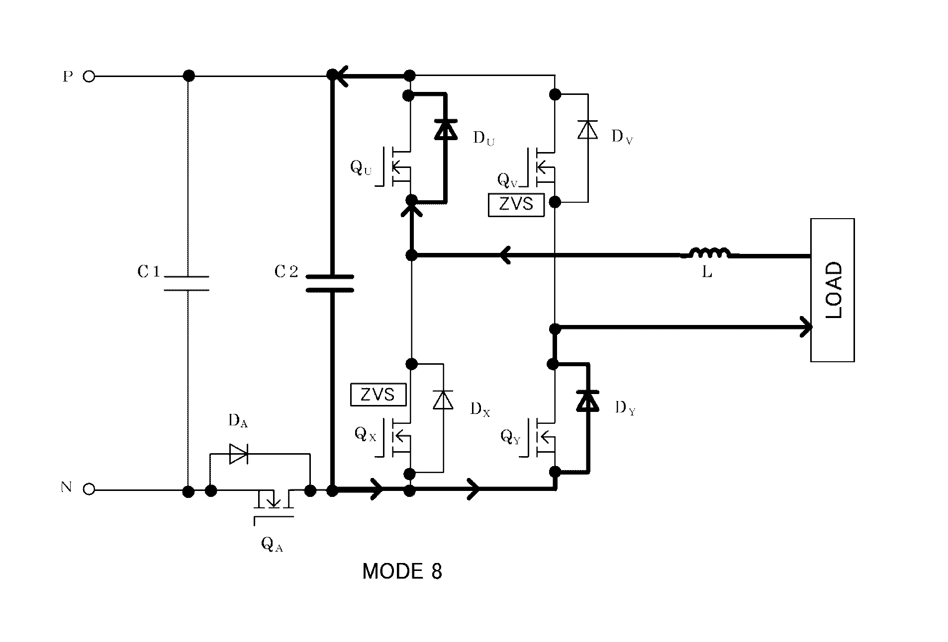
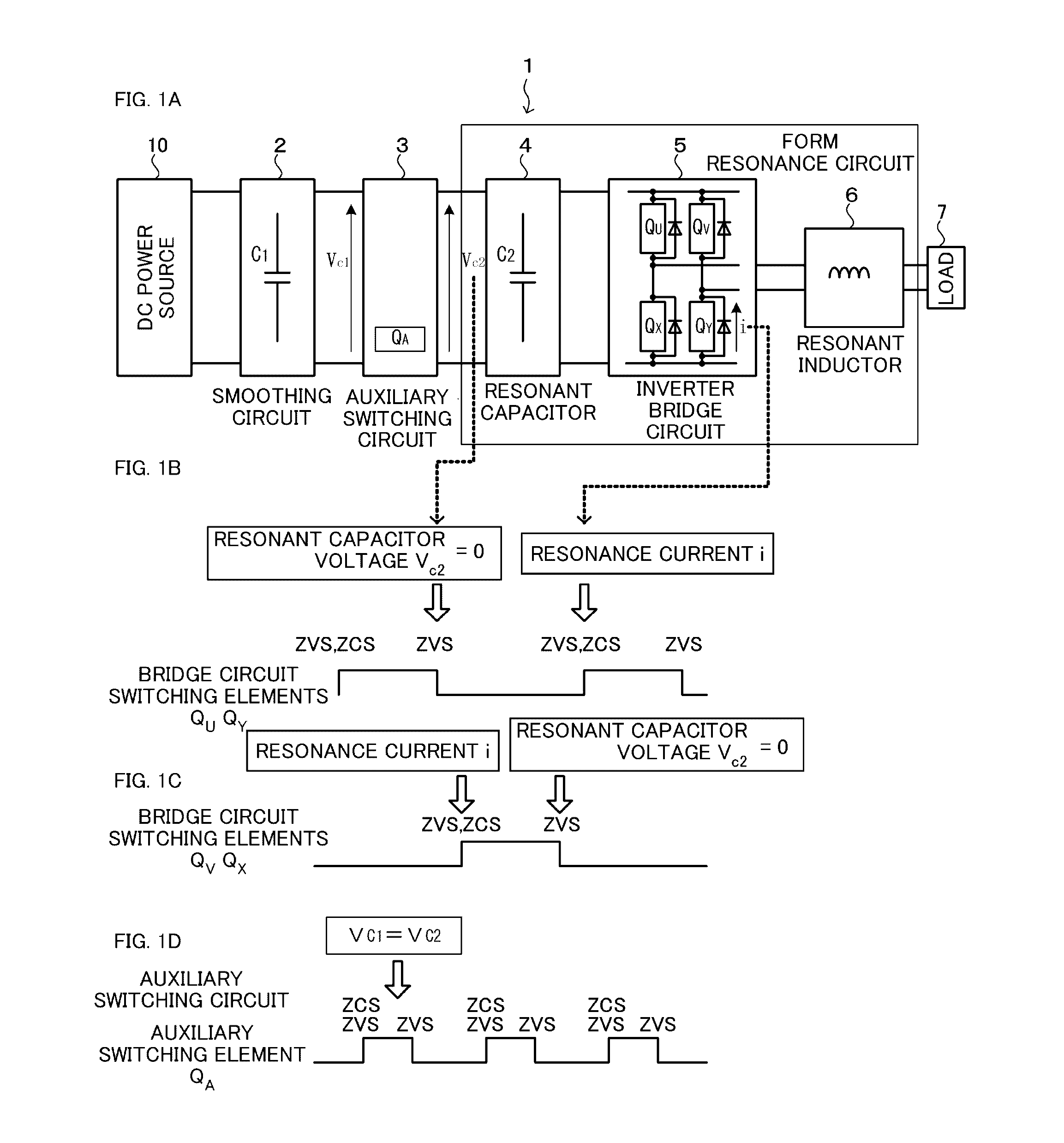
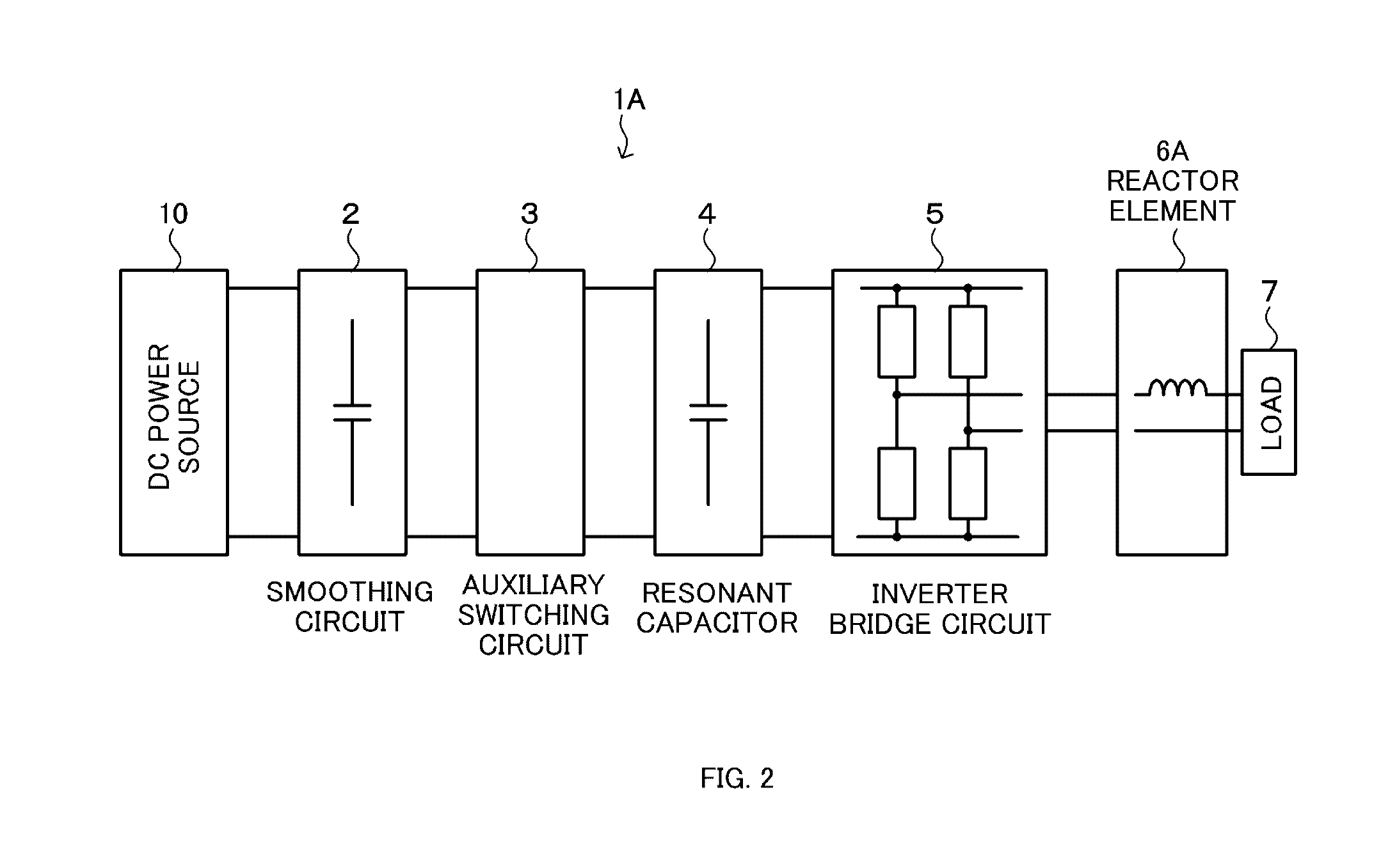
[0061]A preferred embodiment of the present invention will be described in detail below, with reference to the accompanying drawings. In the following, the single phase inverter of the present invention will be described. With reference to FIG. 1 and FIG. 2, a schematic configuration example of the single phase inverter of the present invention will be described, with reference to FIG. 3, a circuit configuration example of the single phase inverter of the present invention will be described, with reference to FIG. 4 to FIG. 16, operation examples of the single phase inverter of the present invention will be described, and a configuration example of a power supply device for plasma, using the single phase inverter of the present invention, will be described with reference to FIG. 17 and FIG. 18.

[Configuration Example of the Single Phase Inverter]

[0062]Firstly, with reference to FIG. 1 and FIG. 2, a schematic configuration example of the single phase inverter of the present invention ...


PUM


Abstract

In an inverter circuit, more particularly in a single-phase inverter, soft switching is performed with a simple configuration to prevent switching loss of a switching element. A resonance circuit is configured by a resonant capacitor provided on the power supply side of a bridge circuit constituting a single phase inverter, a resonant inductor provided on the output side of the bridge circuit, and the bridge circuit. A resonance current passing through the resonance circuit allows zero voltage switching (ZVS) and zero current switching (ZCS) to be implemented at the rising time of main switching elements constituting the bridge circuit, and the zero voltage switching is implemented by means of zero voltage of the resonant capacitor at the falling time of the main switching elements constituting the bridge circuit.

Description

TECHNICAL FIELD[0001]The present invention relates to a single phase inverter that is usable as a power source to supply current to a load, such as a plasma load.BACKGROUND ART[0002]As an inverter to convert DC power to AC power, a voltage source inverter and a current source inverter are well known. The voltage source inverter performs switching by a solid state switch, between a load and a DC voltage source, thereby supplying a square wave alternating current to the load, functioning as the voltage source.[0003]As one configuration of the inverter, there is known a circuit configuration that an arm of abridge circuit is formed with an inverse-parallel connection between a switching element such as a transistor and a thyristor, and a feedback diode, and PWM control is applied to each switching element, whereby DC-AC conversion is performed.[0004]FIG. 19 is a circuit diagram for describing a general configuration of the single phase inverter circuit. As shown in FIG. 19A, in the sin...

Claims


Application Information

Patent Timeline
IPC IPC(8): H02M7/04H02M1/34
CPCH02M7/04H02M1/34H02M7/48H02M7/5387Y02B70/10H02M7/4815
Inventor YUZURIHARA, ITSUOKODAMA, SHINICHIADACHI, TOSHIYUKI
Owner KYOSAN ELECTRIC MFG CO LTD
Why Eureka
Try Eureka