
Welding head and method for joining a workpiece

a welding head and workpiece technology, applied in the field of welding heads, can solve the problems of not taking into account the modification of the position of the component due to the clamping device, the need for manual modification of the reference data, and the measurement error

Active Publication Date: 2016-10-27
PRECITEC GMBH
View PDF16 Cites 3 Cited by
  • Summary
  • Abstract
  • Description
  • Claims
  • Application Information

AI Technical Summary

Benefits of technology

The invention provides a welding head and method for joining a workpiece in a way that allows for easy monitoring of the joint seam during the joining process. The welding head has a beam splitter that allows for easy coupling of a camera with the laser beam path, making it easier to monitor the joining process. The use of a single camera is preferred for cost and simplicity.

Problems solved by technology

In this method, however, in the event of path changes between the reference and measurement runs, elaborate manual modification of the reference data is necessary.
Furthermore, component deviations and modifications of the component during the joining process are not able to be recorded and therefore lead to measurement errors.
Furthermore, modification of the component position due to clamping devices is not taken into account.

Method used


Image

  • Welding head and method for joining a workpiece
  • Welding head and method for joining a workpiece
  • Welding head and method for joining a workpiece

Examples


Embodiment Construction

[0039]In the various figures of the drawing, components which correspond to one another are provided with the same references.

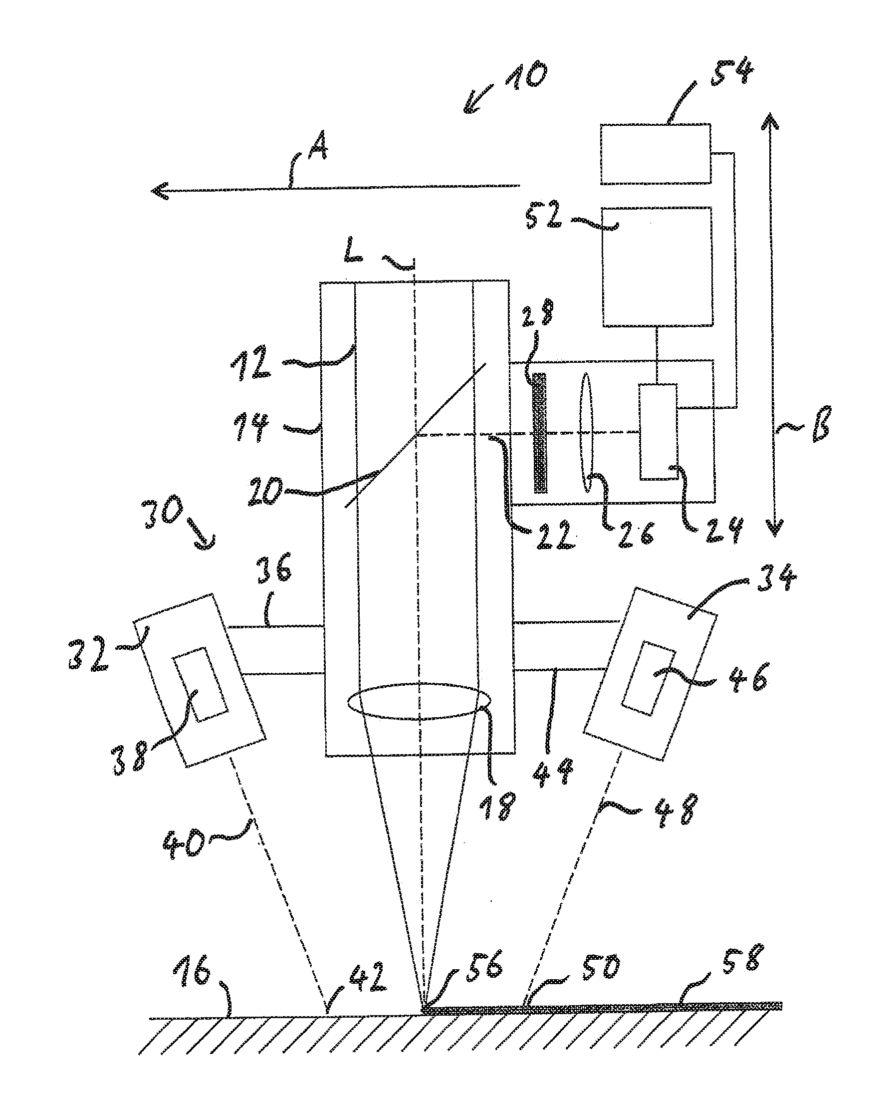
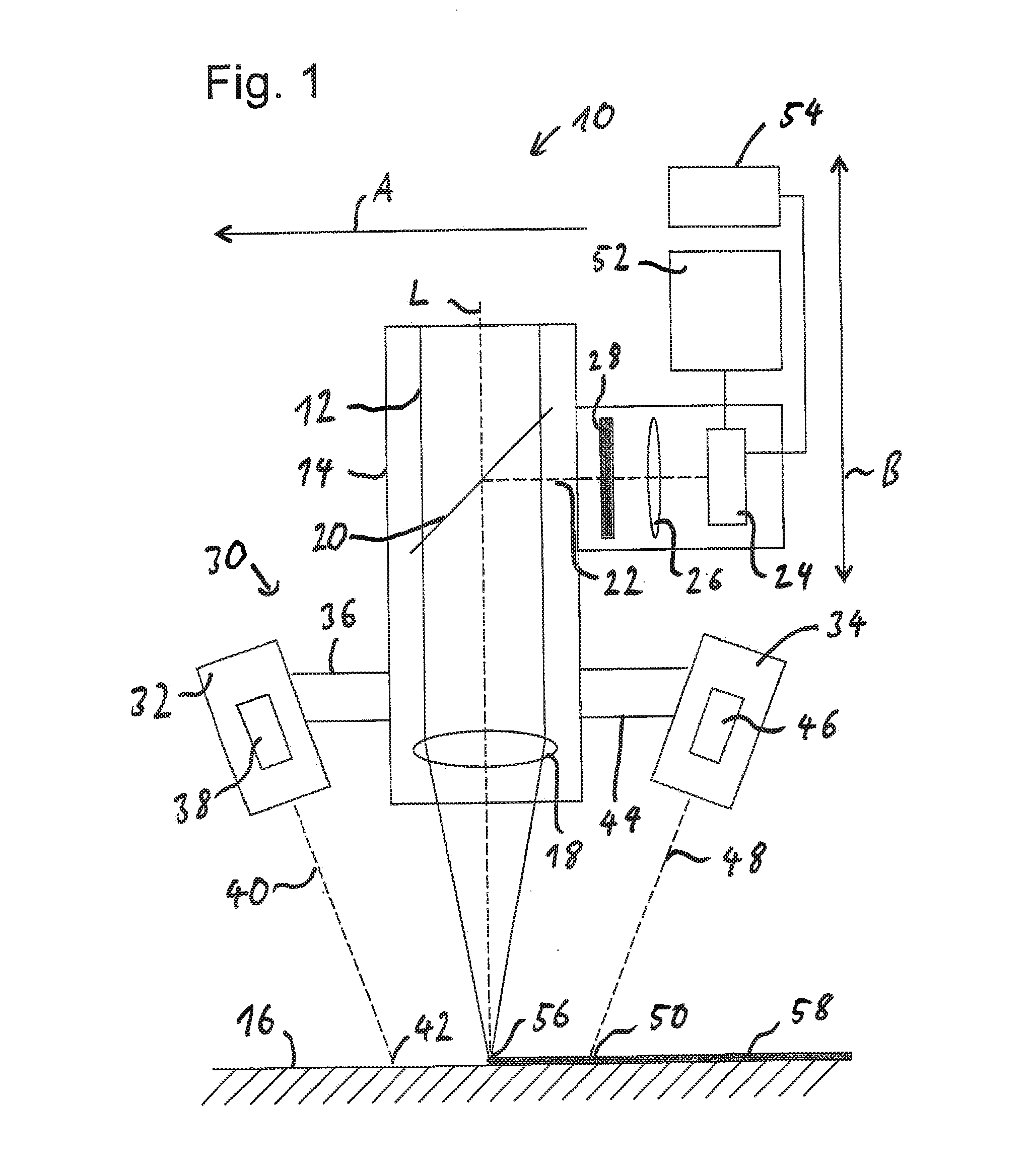
[0040]FIG. 1 shows a highly simplified view of a welding head 10, in particular a laser welding head, according to an exemplary embodiment of the invention, in the way it is used with laser processing machines or systems. A working laser beam 12 coming from the laser processing machine is directed through a housing 14 of the welding head 10 onto a workpiece 16 and focused by means of focusing optics 18 onto the workpiece 16, as indicated by the optical axis L. The working laser beam 12 may be broadened, in the case of supply to the welding head 10 by means of a light guide fiber, owing to the extraction of the laser beam from the light guide fiber by collimator optics.

[0041]Instead of a laser welding head, a metal shielding gas welding head may also be used as the welding device, in which case two cameras (not shown) are used in order to observe the workpiece...


PUM

PropertyMeasurementUnit
wavelength rangeaaaaaaaaaa
emission poweraaaaaaaaaa

Abstract

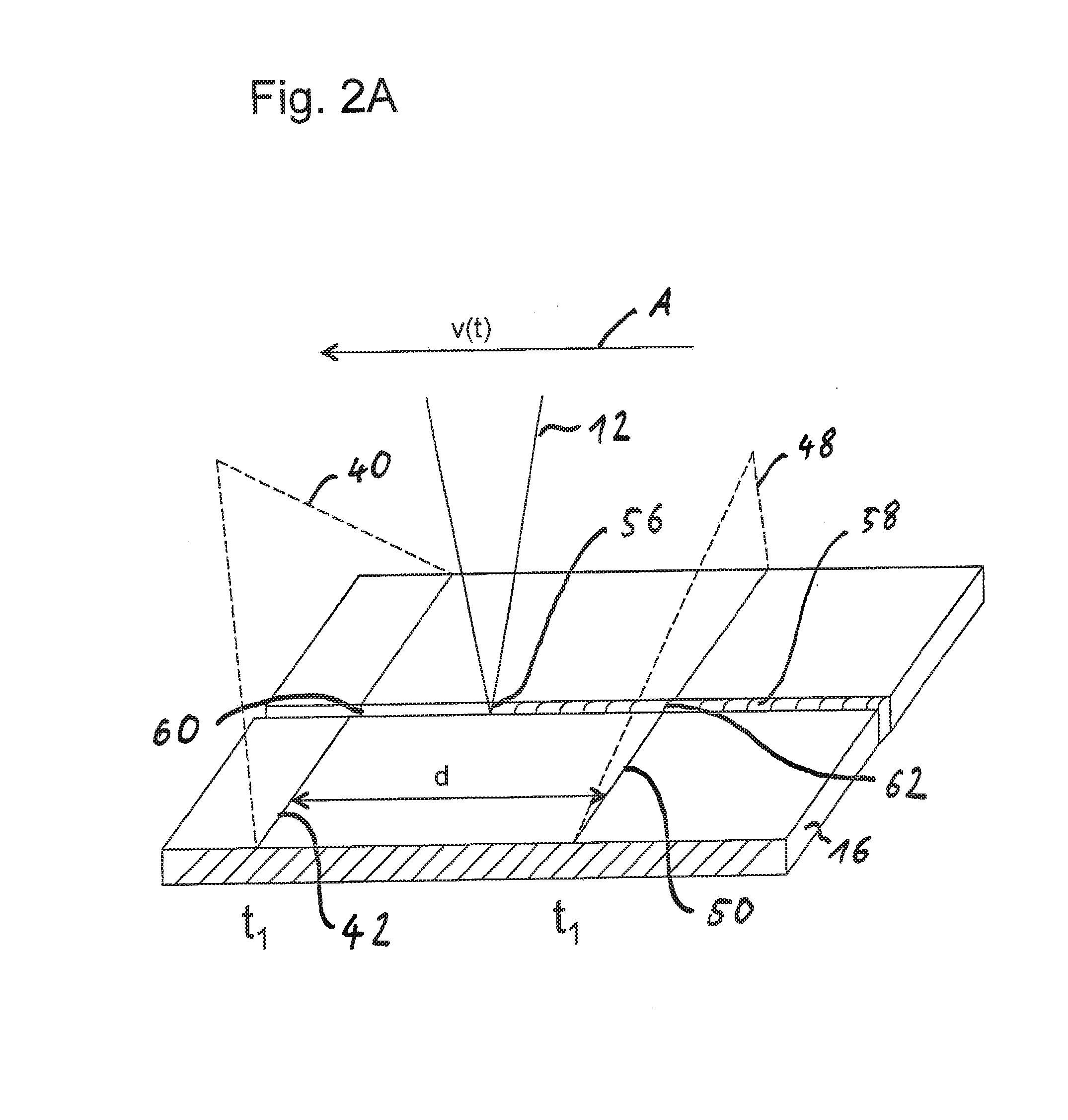
A method for joining a workpiece by means of a welding head, in which at least one line of light is generated on a workpiece, which crosses a joint line at a site to be joined and a joint seam generated at a joined site after processing. The lines of light are imaged at the site to be joined and at the joined site in order to generate reference data relating to the geometry of the site to be joined and measurement data relating to the geometry of the joined sites. The reference data and the measurement data are then compared at one and the same workpiece site before and after processing, in order to determine the geometry of the joint seam independently of the geometry of the site to be joined. t

Description

CROSS-REFERENCE TO RELATED APPLICATIONS[0001]This application is a Continuation of co-pending application Ser. No. 13 / 498,110 filed on May 29, 2012, which is a U.S. National Stage of International Application No. PCT / EP2010 / 005832 filed on Sep. 23, 2010, for which priority is claimed under 35 U.S.C. §120; and this application claims priority of Application No. 10 2009 042 986.7 filed in Germany on Sep. 25, 2009 under 35 U.S.C. §119; the entire contents of all of which are hereby incorporated by reference.BACKGROUND OF THE INVENTION[0002]1. Field of the Invention[0003]The invention relates to a welding head, in particular a laser welding head, and to a method for joining a workpiece, in particular by means of a laser beam, by welding or by soldering.[0004]2. Brief Discussion of the Related Art[0005]With the aid of a laser welding head, a workpiece can be processed by using a laser beam, in which case, for example, welding or soldering work may be carried out in order to join a gap in...

Claims


Application Information

Patent Timeline
Patent Type & Authority Applications(United States)
IPC IPC(8): B23K26/03G01B11/14B23K26/12B23K31/12B23K26/044
CPCB23K26/032B23K31/125G01B11/14B23K26/12B23K26/044B23K26/03G01B5/0037G01B11/0608G01B11/25
Inventor SCHWARZ, JOACHIM
Owner PRECITEC GMBH
Learn More