Novel copper and steel composite pipe, manufacturing method, application and welded structure body

a technology of composite pipes and copper and steel, applied in the field of welding, can solve the problems of limiting the application of existing processes, affecting the service life of the pipeline system, and affecting the service life of the pipeline system, and achieve the effect of greatly restricting the actual application

Active Publication Date: 2016-10-27
ZHUJI SIBEIDA MACHINERY CO LTD
View PDF7 Cites 11 Cited by
  • Summary
  • Abstract
  • Description
  • Claims
  • Application Information

AI Technical Summary

Benefits of technology

[0008]This invention provides a novel copper and steel composite pipe, a manufacturing method, application and a welded structure body for solving the problems that the existing welding effect of a copper pipe and a steel pipe is poor and the actual application is greatly limited.

Problems solved by technology

However, when such product with copper plated on steel and the copper pipe are subjected to flame brazing, the phenomenon of shedding of a plated layer after burn-in exists, and the shed plated layer can cause the serious results of blockage of the pipeline system and jamming of the compressor when entering the pipeline system of the air conditioner.
In addition, the way of plating copper on the steel product is not environment-friendly and liable to produce waste gas and waste water, so that the existing application of the process is greatly restricted.
In the long-term using process of the product, fatigue rupture of the weld seam is liable to occur, and the actual application of a copper-steel butt welded pipe is also greatly restricted.

Method used


Image

  • Novel copper and steel composite pipe, manufacturing method, application and welded structure body
  • Novel copper and steel composite pipe, manufacturing method, application and welded structure body
  • Novel copper and steel composite pipe, manufacturing method, application and welded structure body

Examples


embodiment 1

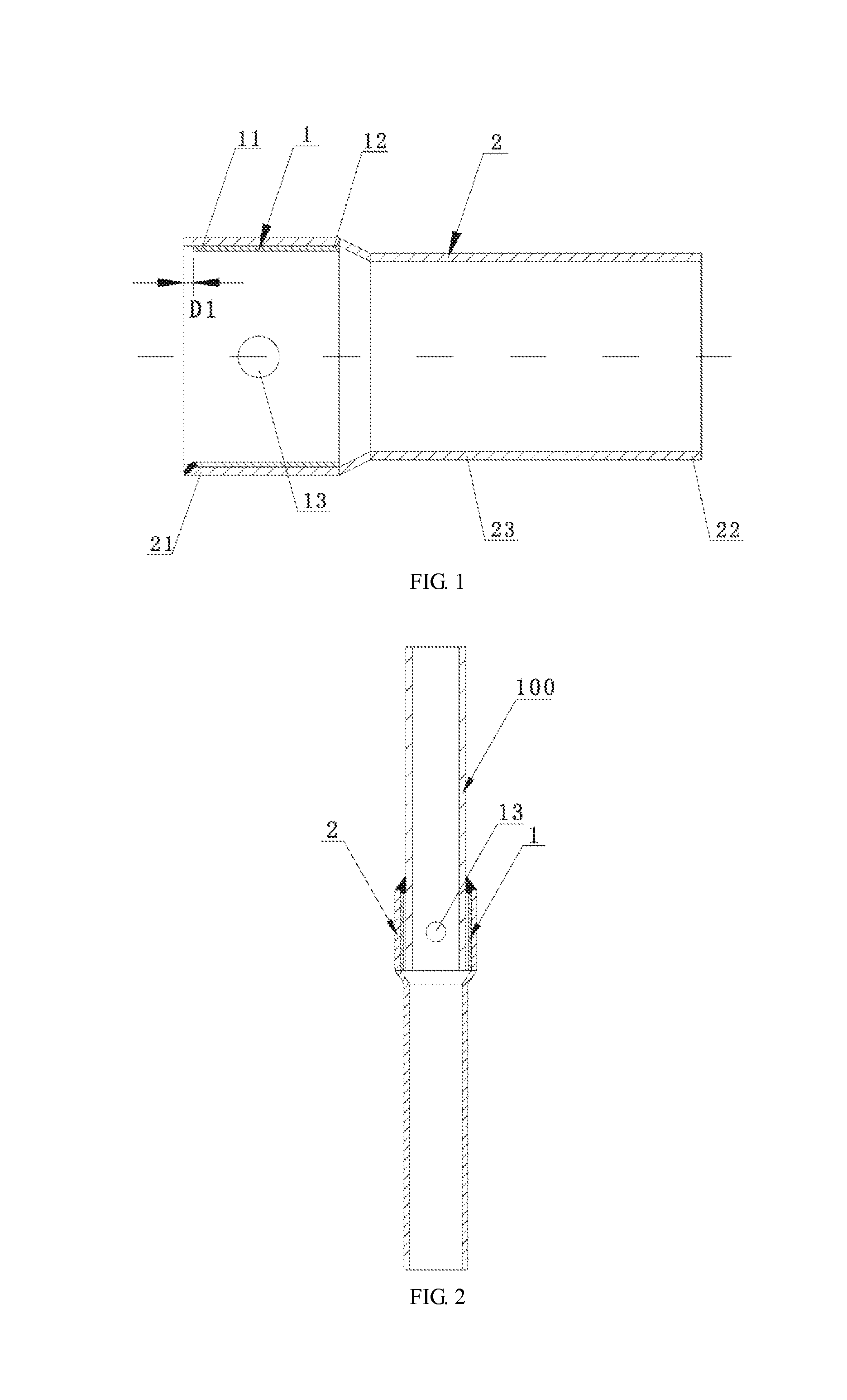
[0045]As shown in FIG. 1, a novel copper and steel composite pipe provided by the embodiment comprises a copper pipe 1 and a steel pipe 2, and the steel pipe 2 comprises a first end 21, a second end 22 and a middle part 23. The copper pipe 1 comprises a first end 11 and a second end 12, wherein the length of the copper pipe 1 is less than that of the steel pipe 2, the copper pipe 1 is partially sleeved on the steel pipe 2, the distance D1 from an end surface of the first end 11 of the copper pipe to an end surface of the first end 21 of the steel pipe is less than 10 mm, the second end 12 of the copper pipe is positioned at the middle part 23 of the steel pipe, and the copper pipe 1 and the steel pipe 2 are welded and connected.

[0046]The steel pipe and the copper pipe provided by the invention are hollow pipe-like parts with certain wall thickness, and the cross section of each of the steel pipe and the copper pipe may be in the shape of a circular ring, an oval ring or other ring c...

embodiment 2

[0066]Please refer to FIG. 8 to FIG. 10 together.

[0067]The embodiment is basically the same as the first embodiment, and the difference lies in that: the copper pipe 1 and the steel pipe 2 are sleeved in such a way that the copper pipe 1 is partially sleeved outside the steel pipe 2. The first end 12 of the copper pipe and the first end 23 of the steel pipe are welded and connected or the second end 12 of the copper pipe and the middle part 23 of the steel pipe are welded and connected.

[0068]In the embodiment, the first end 11 of the copper pipe and the first end 21 of the steel pipe are welded and connected, and before welding, the first end 11 of the copper pipe and the first end 21 of the steel pipe are set to be flush. However, the invention is not limited thereto. In other embodiments, only the second end 12 of the copper pipe and the middle part 23 of the steel pipe are welded and connected, or in order to realize higher connection strength, the first end 11 of the copper pipe...

embodiment 3

[0070]The embodiment is basically the same as the first embodiment, and the difference lies in that: the copper pipe 1 is totally sleeved outside the steel pipe 2. As shown in FIG. 11, both the first end 11 and the second end 12 of the copper pipe are positioned at the middle part of the steel pipe 2, and the copper pipe 1 and the steel pipe 2 are welded and connected in a way of melting base materials. Specifically, the first end 11 of the copper pipe and the middle part of the steel pipe 2 are welded and connected, and the second end 12 of the copper pipe and the middle part of the steel pipe 2 are welded and connected.

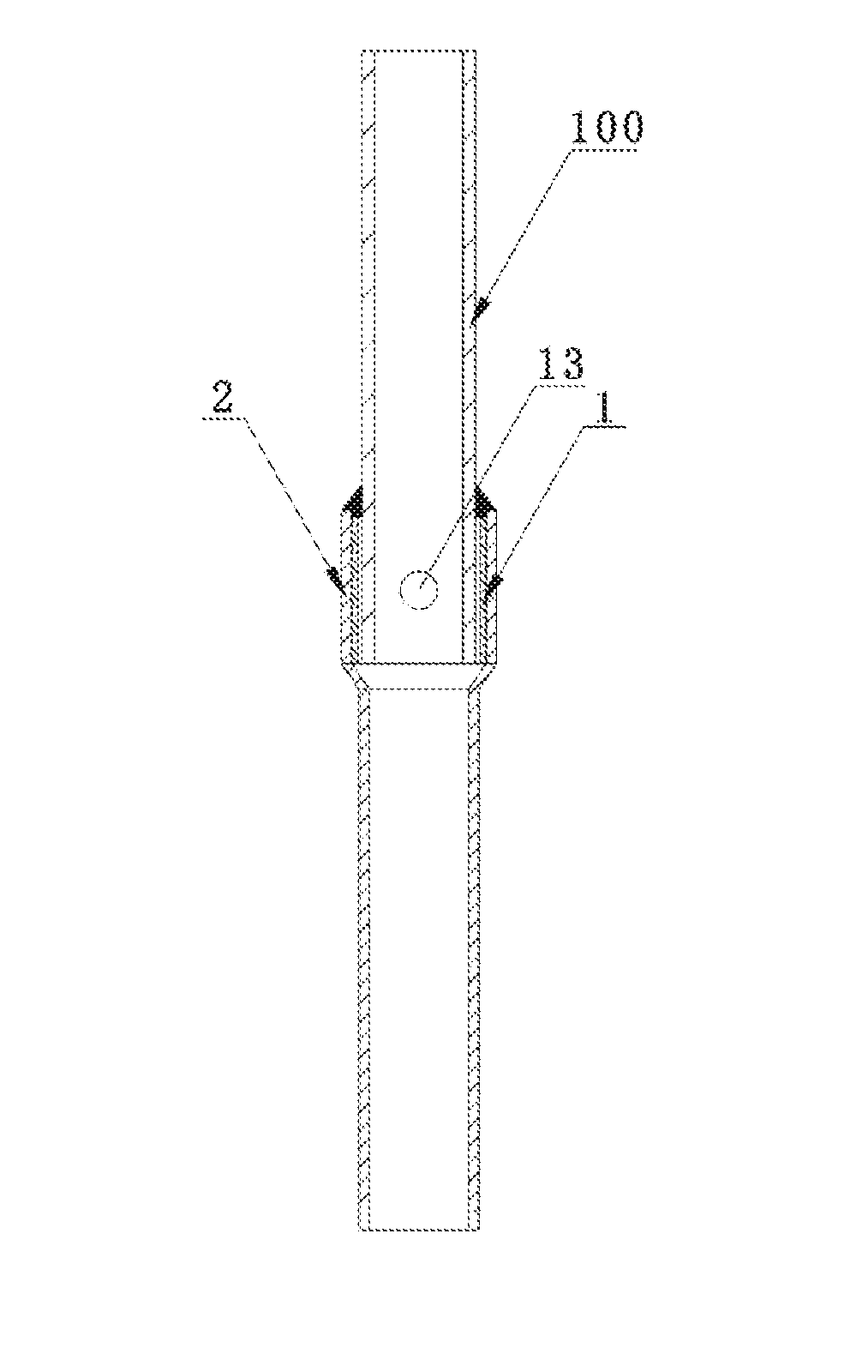
[0071]FIG. 11a is a structure schematic diagram showing a welded structure body formed by the novel copper and steel composite pipe as shown in FIG. 11 and a copper component 100. The copper component 100 is sleeved outside the novel copper and steel composite pipe and corresponds to the copper pipe 1 of the novel copper and steel composite pipe, and the novel coppe...


PUM

PropertyMeasurementUnit
self-melting temperatureaaaaaaaaaa
temperatureaaaaaaaaaa
distanceaaaaaaaaaa

Abstract

A novel copper and steel composite pipe, a manufacturing method, application and a welded structure body is described herein. The novel copper and steel composite pipe includes a copper pipe and a steel pipe. The steel pipe includes a first end, a second end and a middle part. The copper pipe includes a first end and a second end. The length of the copper pipe is less than that of the steel pipe. The copper pipe and the steel pipe are sleeved. The distance from an end surface of the first end of the copper pipe to an end surface of the first end of the steel pipe is less than 10 mm. The second end of the copper pipe is positioned at the middle part of the steel pipe, and the copper pipe and the steel pipe are welded and connected in a way of melting base materials.

Description

BACKGROUND OF THE INVENTION[0001]1. Field of the Invention[0002]This invention relates to the technical field of welding and, more particularly, relates to a novel copper and steel composite pipe, a manufacturing method, application, and a welded structure body.[0003]2. Description of the Related Art[0004]With development of society, national energy-saving and consumption-reducing policies are promoted continuously, in every industry, resources are continuously saved and energy consumption is continuously reduced, but in the refrigeration industry, a precious metal with good plasticity and strength, namely copper, has always been used as a main raw material for production and processing. In the development course of the industry in these years, many scientists performed research work on substitution of various materials. Thus, an extremely urgent event which is conductive to the industry and the national development is to find a material which has not only a certain strength, but al...

Claims


Application Information

Patent Timeline
Patent Type & Authority Applications(United States)
IPC IPC(8): F16L9/02F16L9/22B23K13/01F16L9/14B23K31/02B23K11/02
CPCF16L9/02B23K31/02F16L9/22B23K13/015F16L9/14B23K11/02B23K9/16B23K9/232B23K10/02B23K11/04B23K11/20B23K20/10B23K20/227B23K26/282B23K26/323B23K2101/06B23K2101/12B23K2103/22F16L13/0245
Inventor SHI, YONGBO
Owner ZHUJI SIBEIDA MACHINERY CO LTD
Why Eureka
Try Eureka