

Method for producing polarizing plate and polarizing plate (as amended)
a technology of polarizing plate and polarizing plate, which is applied in the direction of polarizing elements, film/foil adhesives, synthetic resin layered products, etc., can solve the problems of difficult to precisely control the removal region, reduced visibility of the lens, and difficult to precisely control the removal area, etc., to achieve excellent surface roughness and a haze of the depolarization region, and minimize fine wrinkles. , the effect of improving appearan
- Summary
- Abstract
- Description
- Claims
- Application Information
AI Technical Summary
Benefits of technology
Problems solved by technology
Method used
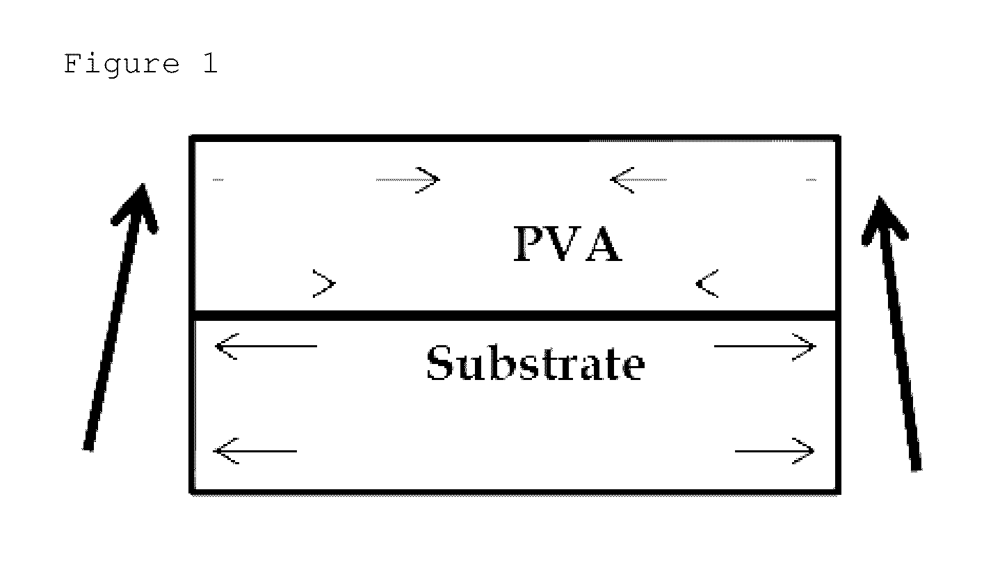
Image

Examples
example 1
[0168]The polyvinyl alcohol-based film (Nippon Gohsei Co., Ltd. M3000 grade 30 μm) was subjected to the swelling process in the pure solution at 25° C. for 15 seconds, and then subjected to the dyeing process in the iodine solution having the concentration of 0.2 wt % at 25° C. for 60 seconds. Thereafter, the polyvinyl alcohol-based film was subjected to the washing process in 1 wt % of the boric acid solution at 45° C. for 30 seconds, and the six time elongation process was then performed in 2.5 wt % of the boric acid solution at 52° C. After elongation, the polyvinyl alcohol-based film was subjected to the complementary color process in 5 wt % of the potassium iodide (KI) solution, and then dried in the oven at 60° C. for 5 minutes, thereby manufacturing the polyvinyl alcohol-based polarizer having the thickness of 12 μm.
[0169]Thereafter, after the acryl-based protection film was laminated on one surface of the polyvinyl alcohol-based polarizer and the masking film where the hole ...
PUM
| Property | Measurement | Unit |
|---|---|---|
| transmittance | aaaaa | aaaaa |
| transmittance | aaaaa | aaaaa |
| area | aaaaa | aaaaa |
Abstract
Description
Claims
Application Information