Method and apparatus for a gesture controlled interface for wearable devices
a wearable device and gesture control technology, applied in the field of wearable devices, can solve the problems of cumbersome and unintuitive human interfaces, keyboards have become cumbersome means of communication, and the approach is limited, and the interfaces of human computers are not based on subtle human skills
- Summary
- Abstract
- Description
- Claims
- Application Information
AI Technical Summary
Benefits of technology
Problems solved by technology
Method used
Image
Examples
embodiment 40
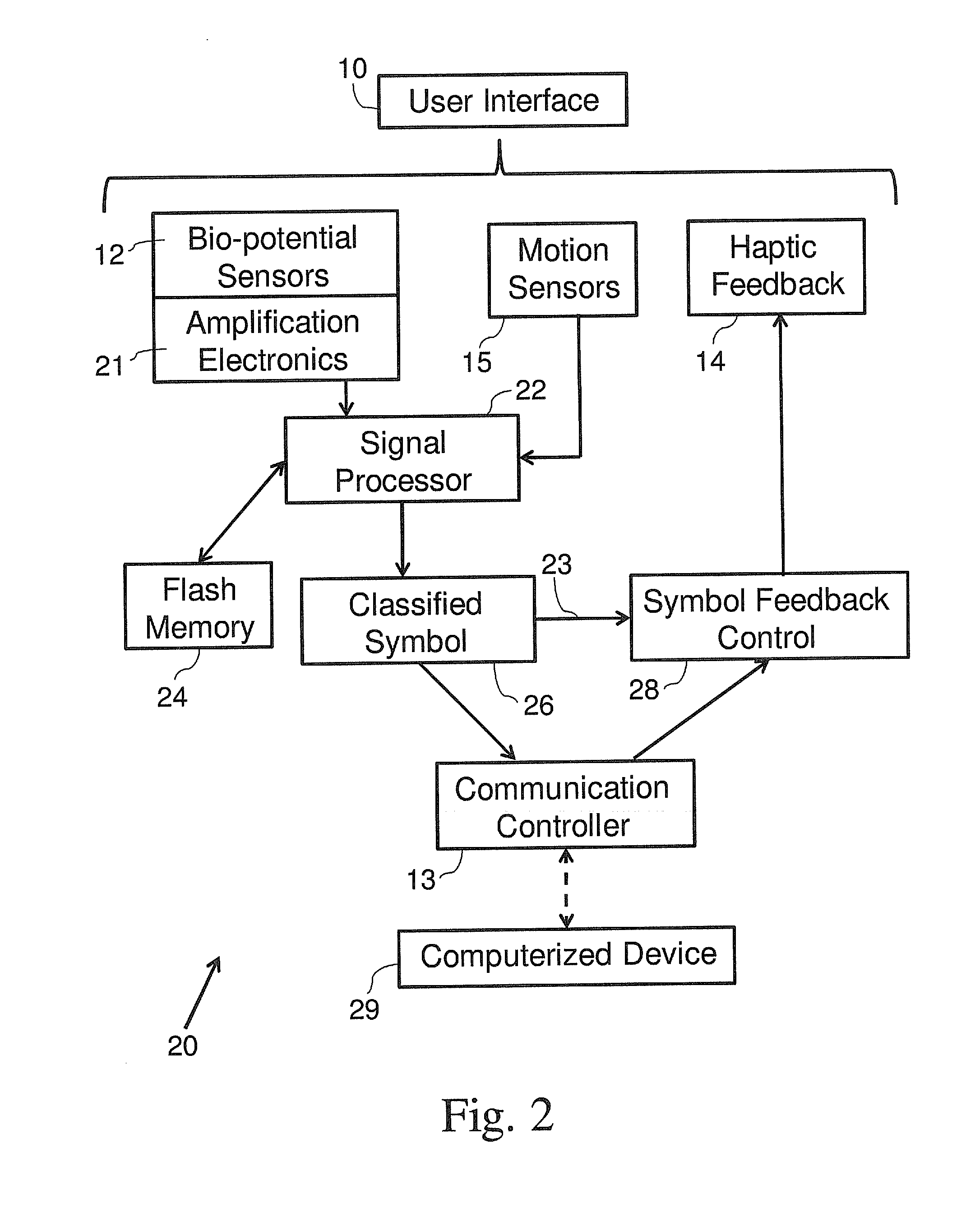
[0095]FIG. 4A depicts a block diagram of a gesture controlled system 40, in accordance with some embodiments of the present invention, wherein all processing is carried out at a computerized device (the direction of the arrows indicates the direction of the information flow). In this embodiment 40, the signal processor 22, the flash memory 24, and the classified symbol 26 are all elements of the computerized device 49.
[0096]A signal from the user interface 43, namely from the bio-potential sensors 12, the motion sensors 15 and / or from the heart rate sensors 32, is transferred as output from an output controller 42 to the communication controller 13. This output may then be transmitted via wireless communication to the computerized device 49 in order to process these signals (as described above). The classified symbol 26 is transferred to a command processor 44 of the computerized device 49 so that the required command may be carried out.
[0097]In the case that a signal is transmitted...
embodiment 41
[0101]FIG. 4B depicts a block diagram of a gesture controlled system 41 with an input / output interface, in accordance with some embodiments of the present invention. The direction of the arrows indicates the direction of the information flow. In this embodiment 41, the sensor array 12 and the haptic feedback actuators 14 function together as a generic input / output (I / O) interface for sensory substitution. In this configuration, electrical signals may be conditioned in the signal processor 22 and fed back directly to an I / O user interface 45 via an electro-tactile and / or vibro-tactile stimulator 48, not requiring a discrete classification. Such I / O interfaces may fully replace or augment various body sensory capabilities. For example, as a camera for the blind, as an inertial measurement unit (IMU) for people with vestibular loss or as a microphone for a deaf user that may be translated into direct tactile sensory input. Such examples and other uses are for instance discussed in Bach...
embodiment 120
[0142]FIG. 10B schematically illustrates a cross-sectional view of an exemplary circuitry of the combined sensor with concentric rings, in accordance with some embodiments of the present invention. A further embodiment 120 shown in FIG. 10B, comprises the reference electrode 108 that includes two concentric rings with an internal electrode 110, and an external electrode 112 separated from the internal electrode 110 by a nonconductive material 111, where the stimulating signal is driven to the internal electrode 110 and the common mode signal is driven to the external ring electrode 112. In some embodiments of the present invention, the skin conductivity of the user's wrist is measured between the two electrodes by measuring the amplitude generated by driving the current through the impedance of the skin with the bio potential sensor. Since the current is constant and controlled by the device, the measured voltage may change according to the skin impedance.
[0143]In some embodiments o...
PUM
 Abstract
Description
Claims
Application Information
 - R&D
- Intellectual Property
- Life Sciences
- Materials
- Tech Scout
- Unparalleled Data Quality
- Higher Quality Content
- 60% Fewer Hallucinations
Browse by: Latest US Patents, China's latest patents, Technical Efficacy Thesaurus, Application Domain, Technology Topic, Popular Technical Reports.
© 2025 PatSnap. All rights reserved.Legal|Privacy policy|Modern Slavery Act Transparency Statement|Sitemap|About US| Contact US: help@patsnap.com


