Each box is individually designed, manufactured, qualification tested for the requirements for a particular vehicle, and specifically mounted
on board that vehicle in a predetermined location, usually in the vicinity of the other
avionics boxes per weight and balance considerations, and collectively occupy substantial mounting space and add significant weight.
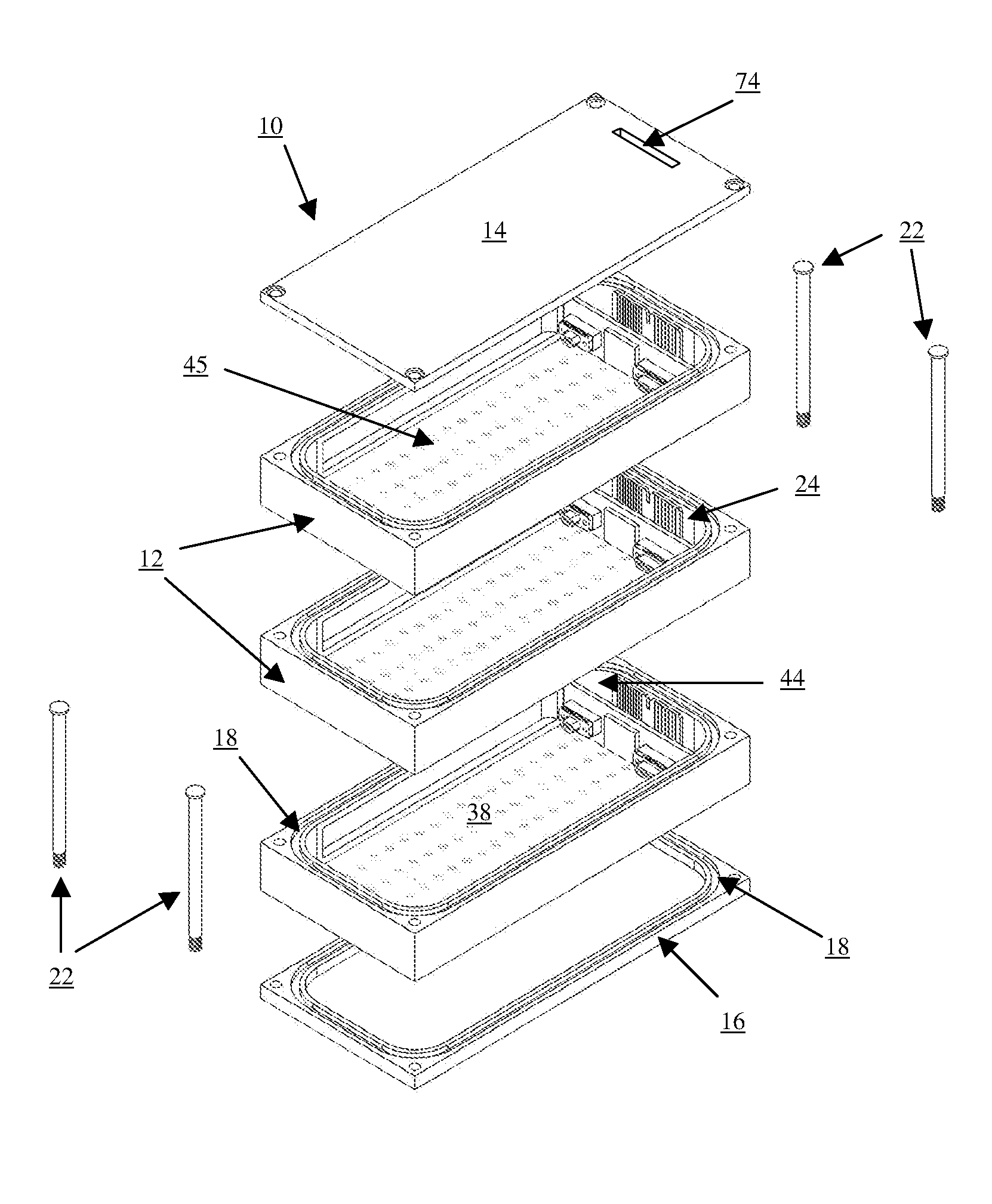
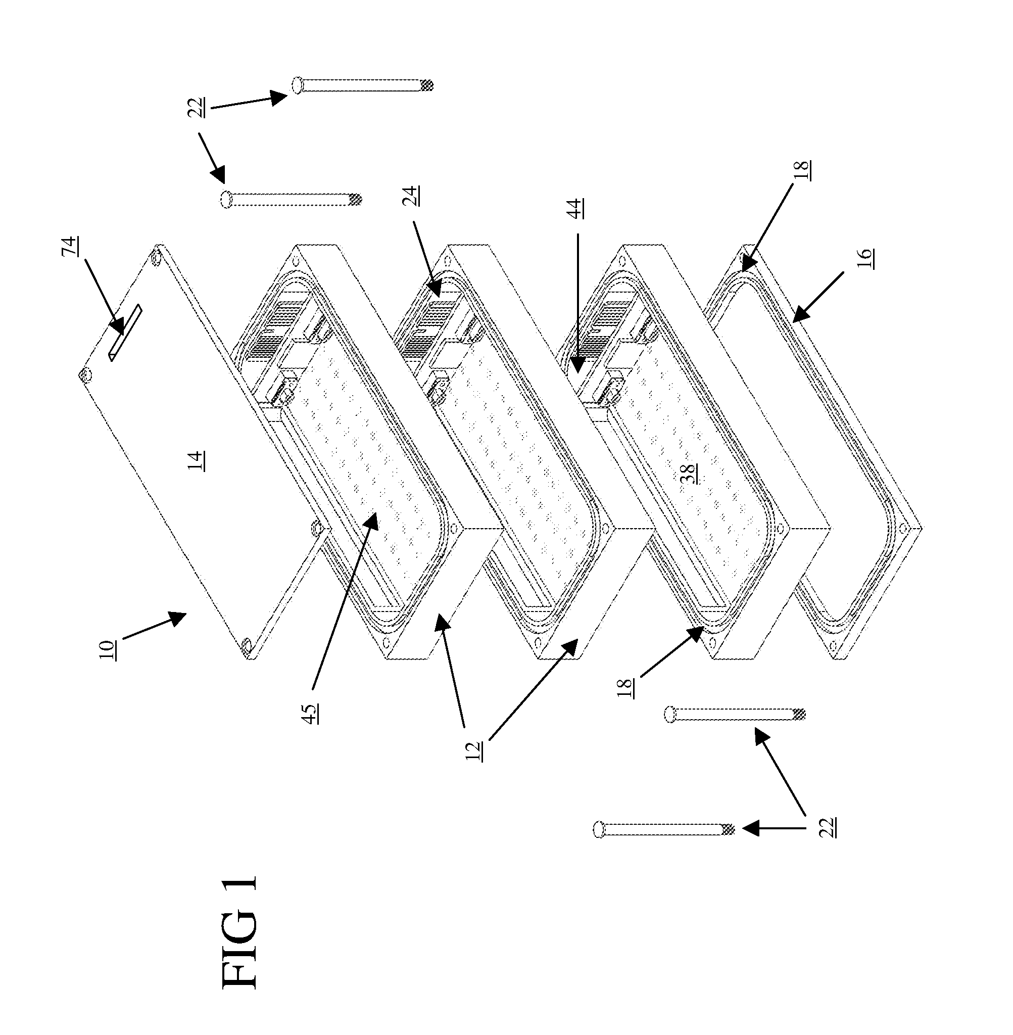
If one desired to simply stack these separate boxes on top of each other up in a vehicle to save
footprint space, it would be impossible to do so due to the individual thermal, structure and cabling requirements of each box, in addition to the diverse size of the boxes, with no common bolt pattern existing for connecting them together.
Furthermore, there is no possibility for these individual boxes to be ganged together to form the structure of a consolidated avionics unit or a free-standing
satellite for the reasons previously listed, which gets even more complicated if one wanted to add deployable solar panels and a propulsion /
attitude control system for orienting the satellite in space.
In addition to the acreage and weight requirements demanded by these federated components, this antiquated approach makes it physically and financially impossible to implement an incremental or full
upgrade of components within these individual black-boxes to meet its new and changing requirements, as these boxes are sold as a sealed single unit with a serial number that relates to exactly what is in that black-box.
Additionally, if an
upgrade is required, the many black-boxes of an avionics suite or the internal workings of a
satellite system forces a customer into the extremely high cost of redeveloping and environmentally qualifying each of the many separate black-boxes which comprise that avionics suite or satellite, consistently resulting in an unnecessary and extremely large cost for an even incremental or minimal
upgrade switch-out to incorporate a newer black-box with a greater capability than the previous one.
Similarly, each
black box is typically only
usable on a
single class of vehicle, and if not space-qualified it cannot be used in a space application, and is therefore restricted for use within atmospheric benign conditions.
Conversely, a typical space-qualified black-box would be cost prohibitive to employ on an aircraft or a vehicle only used in benign atmospheric conditions from the earth's surface on up into typical aircraft altitudes.
There are however a very limited number of inventions addressing modular systems, battery packs and modular
control electronics for batteries being one of them.
(a) No federated black-box avionics system or satellite incorporates a methodology for isolating / combining / reconfiguring internal components either physically or via
software command in an integrated fashion in the event that mission requirements change, in addition to it being impossible to instantly adapt these federated black-boxes into a single stacked satellite structure
bus.
(b) The failure of a single black-box in a federated aerospace avionics suite or satellite has the
high likelihood of jeopardizing a mission resulting in a
system failure, as it is not possible to automatically protect the system with workarounds which could be automatically implemented because of the proprietary nature of each individual black-box making up the avionics suite or satellite.
(c) There is no single common system available to provide real-time monitoring / feedback of the health and status of all components within an array of avionics black-boxes or of a satellite, thus generating the need for a vast array of costly proprietary
ground support equipment.
(d) The limiting architecture and design of existing federated black-box systems presently in use with avionics or satellites preclude the rapid integration of external sensors or other sources in an instant
interfacing manner.
(e) No capability exists to restructure in real-time the interaction of two or more federated black-boxes within a federated avionics system, either within a satellite or avionics suite application, and certainly none exists that can be commonly utilized with both.
(f) In addition to inefficiencies that accompany the limiting factors encountered in fielding today's federated avionics or satellite systems, their ‘antiquated upon delivery’ nature also lends themselves to significant operations / maintenance issues and costs required to independently recondition and service components within the federated black-boxes of an avionics suite or satellite.
(g) The closed and proprietary nature of today's federated / only partially integrated modular aerospace and avionics hardware systems is firmly based upon obsolete technology with long-
lead time architecture by its very nature, and is often size, weight and power (SWAP) excessive when compared to the rapidly evolving technologies which cannot be integrated and consolidated without major redesign and a prohibitive cost.
(h) Present avionics suites and satellites are limited to their individual unique manufacture, and do not allow for their rapid reconfiguration to a larger / smaller capacity, either physically or electronically.
(i) All present avionics systems negate the possibility of
morphing their configuration into a modular and consolidated arrangement, thus increasing their design, implementation and qualification costs.
(j) Extreme launch environments cause present avionics systems with multiple black-boxes to undergo costly individualized pre-
qualification testing to mitigate potential problems from surfacing during the operational employment of their fully fractionalized system.
(k) Present federated avionics system architectures do not allow for a method of control aside from the immediate systems they are employed within, thus eliminating the possibility of mesh
network control if in use with a satellite, and also preclude redundant fail-over switching and
fault tolerance.
(l) Currently deployed federated avionics systems are incapable of providing integrated predictive and real-time monitoring of health and status, thus precluding the capability to head-off and work-around an internal failure before it happens.
(m) Federated avionics systems with multiple black boxes as currently arranged in
aerospace systems are not capable of being quickly combined with other
system hardware in real-time in the event of a change in mission requirements or a change in external interfaces.
(o) Space rated environmental
qualification testing is complex and plagues all multiple black-box designs, forcing the designer into expensive qualification re-testing programs that have major schedule and cost impacts even if a tiny component and / or subsystem within a black-box is removed, changed or modified.
(p) Today's federated avionics systems comprised of multiple black boxes cannot accommodate the capability for a collective and integrated predictive tool to be implemented with all boxes due to a lack of their standardized mechanical and electrical interfaces.
(q) Impacts of size and weight constantly arise during employment of existing multiple black-box systems, often resulting in the sacrifice of other mission capabilities.
(r) Simultaneous conditioning, reconfiguring, query, reset, work-around and initializing on a collective basis is not possible with a federated black-box system.
(s) Current avionics and satellite systems cannot and do not combine processor, data communication and I / O, RF (
wireless communication) and power devices in one single non-federated system that can pass rigorous environmental (thermal, random and sine vibration, shock, etc.) and EMI / RFI testing.
(t) Present avionics systems are separately designed / built for two separate and distinct realms of operation, that of being used within the benign atmospheric conditions or the harsh environment of space, while none can accommodate both environments in a practical and cost-effective way.
(u) The federated black-box avionics systems of today cannot be integrated into a single unit for passing space
qualification testing.
(v) All existing and not even yet fielded modular systems described in the above prior art are not able to accommodate RF devices internally in the vicinity of a power system without extensive additional shielding, and are thus not completely open, modular, scalable, and reconfigurable, and thereby do not approximate the intent or capabilities of this invention.
(w) No proposed modular systems of the prior art incorporate individual EMI chamber modules that
interlock for simultaneously creating at least two instant faraday cages, and while being a shock / vibration immune
enclosure that is expandable.
(x) All federated black-box avionics systems employ an
interconnection system that is external to the individual black-boxes, and thus manifest a definite and inherent
weakness that cannot be surmounted if full space qualification testing is desired.
(y) Current federated black-box avionics systems cannot be employed for use on different aircraft or satellites without re-
engineering for the particulars related to the locations, power and mounting surfaces in the new vehicle.
(z) Federated black-box avionics systems in space are vulnerable to external physical
attack due to their
large size that results from the overall additive sizes of their individual black-boxes.
Additionally, the methods proposed by Jung Soon Jangt / Claire J Tornlint and Rene L. C. Eveleens actually do nothing to advance the art whereby they left out the most important and to this day unsolvable methods of integrating RF (
wireless communication) functions with power, processor, I / O, EMI and RFI isolation into a single unit which can be instantly used within or outside the
atmosphere without any modification and instantly pass space qualification testing as a single consolidated unit for operating in any environmental regime in the role as either an avionics system or as a stand-alone satellite.

