Ultrasonic diagnostic device

a diagnostic device and ultrasonic technology, applied in the field of ultrasonic diagnostic devices, can solve problems such as excessive contrast, and achieve the effect of enhancing the boundary and increasing the visibility of the boundary of the tissu

Inactive Publication Date: 2016-11-10
HITACHI LTD
View PDF1 Cites 9 Cited by
  • Summary
  • Abstract
  • Description
  • Claims
  • Application Information

AI Technical Summary

Benefits of technology

[0016]The present invention provides a technique for enhancing a boundary within an ultrasound image using multiresolution decomposition. In accordance with a preferred aspect of the invention, the visibility of boundaries of a tissue can be increased without impairing information inherent in an ultrasound image.

Problems solved by technology

With these techniques, however, not only the boundaries for which enhancement is desired but also other parts for which enhancement is not necessary, such as noise, may be enhanced, and also parts having a sufficient contrast may be enhanced to thereby have excessively increased contrast.

Method used


Image

  • Ultrasonic diagnostic device
  • Ultrasonic diagnostic device
  • Ultrasonic diagnostic device

Examples


Embodiment Construction

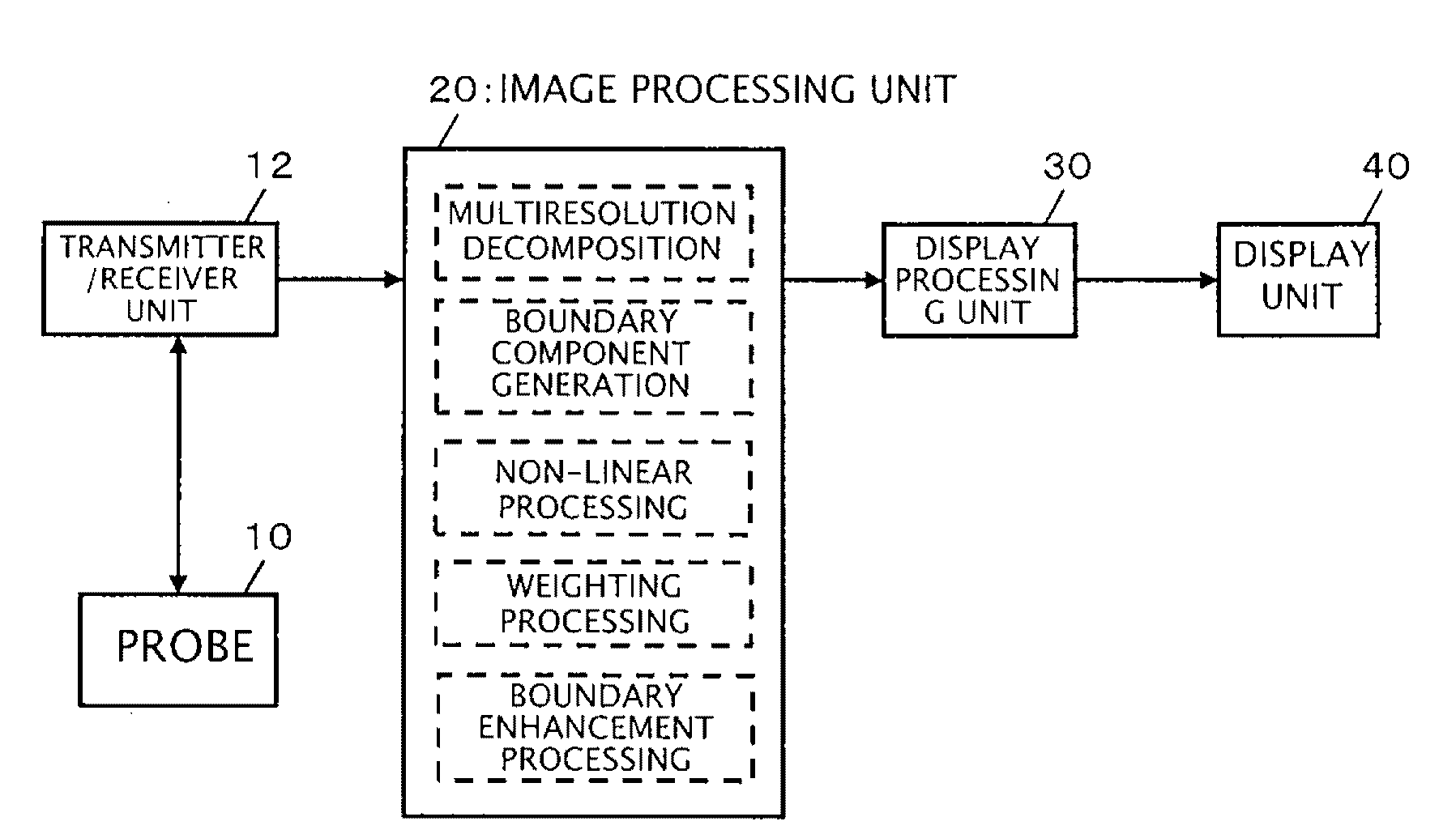
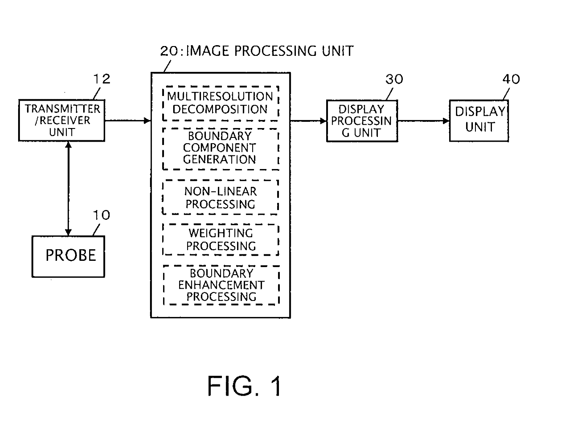
[0041]FIG. 1 is a diagram illustrating an overall structure of an ultrasound diagnostic device which is suitable for implementation of the present invention. A probe 10 is an ultrasound probe which transmits and receives ultrasound to and from an area including a subject for diagnosis, such as a heart, for example. The probe 10 includes a plurality of transducer elements, each of which transmits and receives ultrasound, and the plurality of transducer elements are controlled by a transmitter / receiver unit 12 for transmission and reception of ultrasound to form a transmitted beam. The plurality of transducer elements also receive ultrasound from the area including the subject for diagnosis and output signals thus obtained to the transmitter / receiver unit 12. The transmitter / receiver unit 12 then forms a received beam and collects echo data along the received beam. The probe 10 scans an ultrasound beam (the transmitted beam and the received beam) within a two-dimensional plane. Of cou...


PUM


Abstract

An image processing unit (20) performs resolution conversion processing on an ultrasound image obtained on the basis of a reception signal, to generate a plurality of resolution images having mutually different resolutions. Furthermore, the image processing unit (20) performs non-linear processing on a difference image obtained by comparing the plurality of resolution images with each other, to generate boundary components related to boundaries included in the image. Moreover, a boundary-enhanced image is generated by performing enhancement processing on the ultrasound image on the basis of the generated boundary components.

Description

TECHNICAL FIELD[0001]The present invention relates to an ultrasound diagnostic device, and more particularly to image processing of an ultrasound image.BACKGROUND ART[0002]Techniques for enhancing a boundary of a tissue, for example, in an ultrasound image obtained by transmitting and receiving ultrasound waves are known (see Patent Documents 1 and 2).[0003]Tone curve modification and unsharp masking are typical examples of specific boundary enhancement techniques that are conventionally known. With these techniques, however, not only the boundaries for which enhancement is desired but also other parts for which enhancement is not necessary, such as noise, may be enhanced, and also parts having a sufficient contrast may be enhanced to thereby have excessively increased contrast.[0004]Patent Document 3 describes a method for improving the image quality of an ultrasound image by multiresolution decomposition with respect to the image.CITATION LISTPatent Literature[0005]Patent Document...

Claims


Application Information

Patent Timeline
Patent Type & Authority Applications(United States)
IPC IPC(8): A61B8/08G06T7/00A61B8/00
CPCA61B8/5215A61B8/5207A61B8/461G06T2207/10132G06T7/0012G06T2207/20192A61B8/4444A61B8/0858A61B8/0883A61B8/5223A61B8/5238A61B8/5246A61B8/5253G06T5/003G06T5/50G06T2207/20016G06T2207/20221G16H50/20G16H50/30
Inventor MAEDA, TOSHINORIMURASHITA, MASARUMATSUSHITA, NORIYOSHINAGASE, YUKO
Owner HITACHI LTD
Why Eureka
Try Eureka