Fire protection of a part made of a three-dimensional woven composite material

a composite material and three-dimensional technology, applied in the direction of liquid fuel engines, machines/engines, efficient propulsion technologies, etc., can solve the problems of not being able to solve the problem of self-extinguishing, the material used is not intrinsically self-extinguishable, and the inability to use fire protection, etc., to achieve reliable and efficacious effect, without degrading the mechanical resistance of the par

Active Publication Date: 2016-11-10
SN DETUDE & DE CONSTR DE MOTEURS DAVIATION S N E C M A +1
View PDF11 Cites 6 Cited by
  • Summary
  • Abstract
  • Description
  • Claims
  • Application Information

AI Technical Summary

Benefits of technology

[0012]An aim of the invention is therefore to guarantee self-extinguishing of a part of a turbine gas engine made of composite material comprising a fiber reinforcement densified by a polymer matrix, for example a fan casing, in an industrializable manner, reliable and efficacious, without degrading the mechanical resistance of the part.

Problems solved by technology

In this way, initial fire trials on fan casings made of composite material have shown that the material used is not intrinsically self-extinguishable (or flame-retardant) and therefore requires imperative protection.
In particular, during this machining several millimeters are cut off the flange zone so that it is impossible to use protection against fire co-injected with the preform, as the latter would be eliminated in several zones and therefore would not sufficiently protect the fan casing against fire.
Currently known fire solutions are generally capable of covering the problem of resistance of structures to fire but do not resolve the problem of self-extinguishing.
Yet, these solutions are not easy to implement and are bulky such that they are not possible in a gas turbine engine. manufacturing a structure made of composite material, during which a layer of CMC (ceramic matrix composite material) is preformed and applied to a mandrel then assembled with parts of the structure.

Method used


Image

  • Fire protection of a part made of a three-dimensional woven composite material
  • Fire protection of a part made of a three-dimensional woven composite material
  • Fire protection of a part made of a three-dimensional woven composite material

Examples


Embodiment Construction

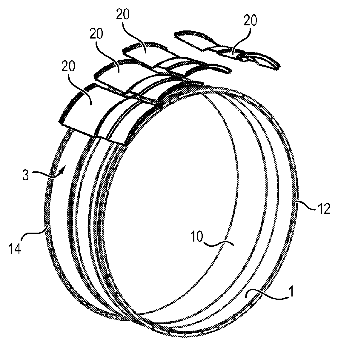
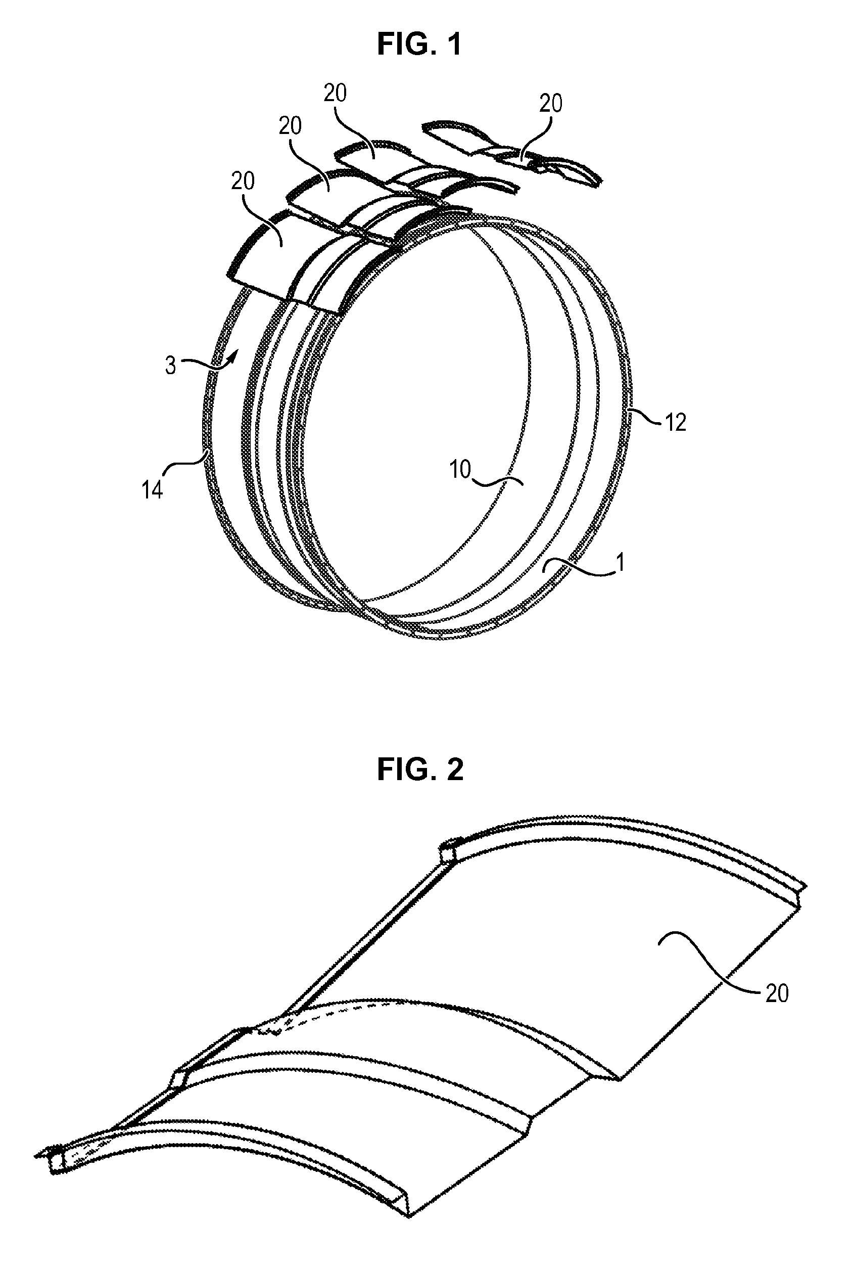
[0031]In the following, the invention will be described more particularly in the case of a fan casing of a gas turbine engine, made of a composite material comprising woven fiber reinforcement, especially three dimensional, densified by a matrix polymer. But it is understood that the invention is not limited to producing such a fan casing but also covers any part of a gas turbine engine made of such composite material.

[0032]A fan casing 1 comprises an overall cylindrical barrel 10, having a main direction extending according to a longitudinal axis X substantially parallel to the gas flow. The barrel 10 of the casing can have a variable thickness, as indicated in document FR 2 913 053, and can be fitted with an upstream flange 12 and a downstream flange 14 at its upstream and downstream ends, respectively, to enable its mounting and its attaching to other parts, including the air inlet sleeve, the intermediate casing or even the annular ferrule.

[0033]The upstream flange 12 and the do...


PUM

PropertyMeasurementUnit
lengthaaaaaaaaaa
axial lengthaaaaaaaaaa

Abstract

The invention relates to a method for fire protection (S) of a part (1) of a gas-turbine engine made of a composite material comprising a main fibrous reinforcement compregnated by a main matrix, the protection method (S) comprising the following steps: preforming (S1) a panel of pre-preg (20) such as to grant same a shape corresponding to the shape of a surface (3) of the part (1) to be protected against fire, said panel of prepreg (20) comprising a secondary fibrous reinforcement compregnated by a secondary matrix; applying (S2) the panel of prepreg (20) thus preformed to the part (1); and securing (S3) the panel of prepreg (20) to the surface (3) by thermal treatment of the part (1) provided with said panel of prepreg (20) in order to obtain a fire-protection layer (2).

Description

FIELD OF THE INVENTION[0001]The invention relates in general to a gas turbine for an aircraft engine comprising a part made of composite material comprising a fiber reinforcement densified by a matrix of a gas turbine such as a retention casing for a fan and its associated production method.TECHNOLOGICAL BACKGROUND[0002]A gas turbine engine generally comprises, from upstream to downstream in the direction of gas flow, a fan, one or more compressor stages, for example a low-pressure compressor and a high-pressure compressor, a combustion chamber, one or more turbine stages, for example a high-pressure turbine and a low-pressure turbine, and a gas discharge tube.[0003]The engine is housed inside a casing comprising several parts corresponding to different elements of the engine. Therefore the fan is enclosed for example by a fan casing and comprises flanges at its axial ends. A first flange, called upstream flange, enables fastening of an air inlet sleeve to the casing, while the seco...

Claims


Application Information

Patent Timeline
Patent Type & Authority Applications(United States)
IPC IPC(8): F04D29/58B29C65/02F04D29/02B29C65/48F04D29/52F04D29/64
CPCF04D29/5853F04D29/522F04D29/644F04D29/023B29C65/48B29C65/02B29L2031/7504F05B2230/60F05B2230/40F05B2260/231F05B2280/6015F05B2280/6003F05B2220/303F05D2300/601F01D25/24F02C7/25F05D2300/603Y02T50/60B29C70/685B29C70/68
Inventor MANDEL, ROBINGONCALVES, EMILIELE BORGNE, BENEDICTEQUILLENT, HELENERIETSCH, JEAN-CHRISTOPHE
Owner SN DETUDE & DE CONSTR DE MOTEURS DAVIATION S N E C M A
Why Eureka
Try Eureka