Multifunctional cement composites with load-bearing and self-sensing properties

a composite material, load-bearing technology, applied in the direction of material analysis, instruments, measurement devices, etc., can solve the problems of cementitious composite materials, increased concern, and different damage modes, and achieve the effect of enhancing the ability to sense damag

Active Publication Date: 2016-11-24
RGT UNIV OF CALIFORNIA
View PDF7 Cites 23 Cited by
  • Summary
  • Abstract
  • Description
  • Claims
  • Application Information

AI Technical Summary

Benefits of technology

[0014]A nano-engineered cementitious composite with capabilities of self-sensing or detecting damage, in addition to its intrinsic load-bearing, structural-use properties. The approach enhances the a...

Problems solved by technology

Cementitious composites, such as concrete pavements, structural components (e.g., beams and columns in buildings), bridge superstructures, foundations, tunnels, and dams, to name a few, are susceptible to different damage modes, which are primarily caused by repeated loading, severe operating environments, and long-term deterioration.
For the case of concrete pavement as an example, there is even greater concern that damage could worsen and occur more frequently with the use of heavier vehicles/trucks or new larger aircraft carrying greater payloads.
Damage to the concrete can stem from unanticipated extreme loads, long-term degradation, fatigue, and environmental effects, among others.
In fact, cracks can form in response to tension, cyclic loads (fatigue), and freeze-thaw cycles.
Specifically, freeze-thaw cycles cause water in the pores of the cementitious matrix to expand (when frozen) and create new cracks or widen existing cracks.
Effects such as these exacerbate damage by allowing water, air, and other chemicals to seep beneath the surface, degrade the passivation layer, and induce corrosion of steel reinforcement bars.
Corrosion byp...

Method used


Image

  • Multifunctional cement composites with load-bearing and self-sensing properties
  • Multifunctional cement composites with load-bearing and self-sensing properties
  • Multifunctional cement composites with load-bearing and self-sensing properties

Examples


Embodiment Construction

1. Introduction

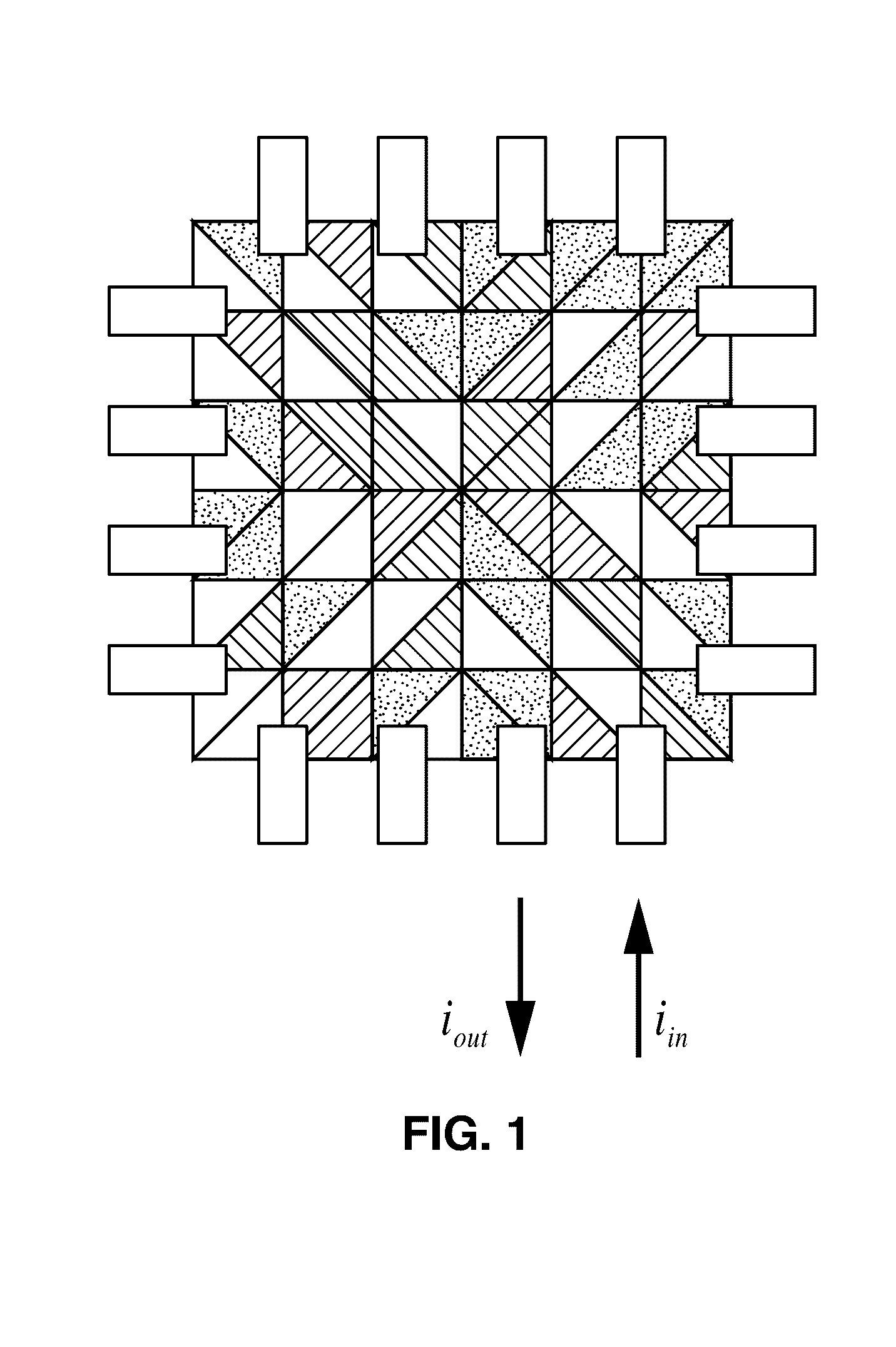
[0028]Concrete and other cementitious composites used in civil infrastructure are prone to numerous forms of damage. For example, cracks can arise and propagate to cause catastrophic component or system level failure. The present disclosure describes a nano-engineered self-sensing cementitious composite that can detect and locate damage.

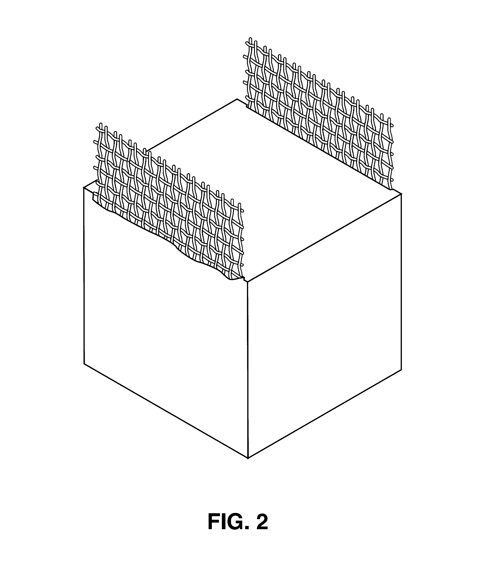
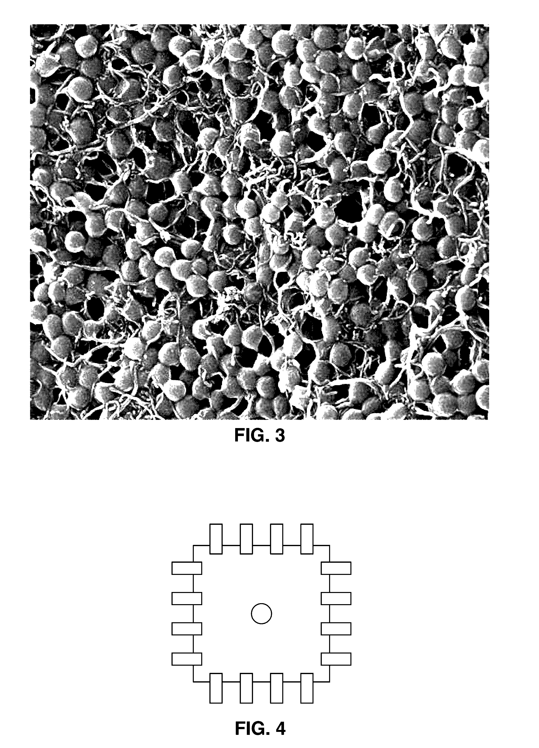
[0029]Conventional methods of creating smart concrete or multifunctional cement composites have basically relied on mixing carbon nanotubes (or other nanomaterials), either in its dry state, dispersed in a solution, or dispersed in superplasticizer solutions, directly with the mix with other raw materials. The underlying concept of these approaches is to disperse nanotubes within the cement composite matrix, such that the nanotubes could interact and form a percolated structure for conducting electricity (and for sensing) and enhancing strength.

[0030]However, a number of disadvantages arise from this approach, including the following. ...


PUM

PropertyMeasurementUnit
Fractionaaaaaaaaaa
Electrical resistanceaaaaaaaaaa

Abstract

A method for creating multifunctional cementitious composites that provide load-bearing and self-sensing properties. The method involves dispersing conductive nanomaterials (e.g., multi-walled carbon nanotubes) into a polymer (e.g., latex) material from which a thin film is created and deposited (e.g., sprayed) onto aggregates, which after drying, can be incorporated with cementitious materials and desired liquids and cast, along with sufficient number of electrodes, into a form for curing. After curing, the resultant structure can be electrically tested through the electrodes, for structural characteristics, including determination of damage severity and location using back-calculation utilizing electrical resistance tomography (ERT), or electrical impedance tomography (EIT), to generate a spatial resistivity map (distribution).

Description

CROSS-REFERENCE TO RELATED APPLICATIONS[0001]This application claims priority to, and the benefit of, U.S. provisional patent application Ser. No. 62 / 165,847 filed on May 22, 2015, incorporated herein by reference in its entirety.STATEMENT REGARDING FEDERALLY SPONSORED RESEARCH OR DEVELOPMENT[0002]This invention was made with Government support under 13-G-017, awarded by the Federal Aviation Administration (FAA), and under CMMI-1200521, awarded by the National Science Foundation (NSF). The Government has certain rights in the invention.INCORPORATION-BY-REFERENCE OF COMPUTER PROGRAM APPENDIX[0003]Not ApplicableNOTICE OF MATERIAL SUBJECT TO COPYRIGHT PROTECTION[0004]A portion of the material in this patent document is subject to copyright protection under the copyright laws of the United States and of other countries. The owner of the copyright rights has no objection to the facsimile reproduction by anyone of the patent document or the patent disclosure, as it appears in the United S...

Claims


Application Information

Patent Timeline
IPC IPC(8): C04B14/02G01N27/04G01N27/20C04B16/06C04B14/06
CPCC04B14/026C04B16/0616C04B14/06C04B2111/00008G01N27/043C04B2111/94G01N27/20C04B20/1029C04B28/02C04B14/005
Inventor LOH, KENNETHGONZALEZ, JESUS
Owner RGT UNIV OF CALIFORNIA
Why Eureka
Try Eureka