
Alignment of flanged components

a technology of flanges and components, applied in the direction of machines/engines, mechanical equipment, liquid fuel engines, etc., can solve the problems of high cost of curvic teeth, inability to ensure the repeatability of rotational or concentric rotation, and inability to achieve assembly repeatability on ipc split casings. , to achieve the effect of reducing the risk of part contamination

Active Publication Date: 2016-11-24
ROLLS ROYCE PLC
View PDF2 Cites 20 Cited by
  • Summary
  • Abstract
  • Description
  • Claims
  • Application Information

AI Technical Summary

Benefits of technology

The patent text describes a new invention for creating compressor segments for turpores. The invention limits the number and way in which adjacent segments can connect, ensuring that they align properly when put together. This results in a more reliable and accurate alignment when putting the segments together, which is important for the performance and efficiency of the compressor. The invention can also be used in other applications, such as in aerospace, and can improve the resilience and maintenance of existing couplings.

Problems solved by technology

Unfortunately, the required repeatability of assembly is not currently achieved on either the IPC split casings and HPC stack casings.
The disassembly and subsequent re-assembly of the casing segments of either the HPC or IPC provides an opportunity for misalignment of the segments after liner machining process, due to required tolerances between the bolts and the flange bolting holes and the absence of other means of providing location of one segment of the split casing structure relative to another.
The bolted flanges in the IPC do not ensure repeatability of axial or concentric alignment between the two halves of the split casing, and the bolted flanges in the HPC do not ensure repeatability of rotational or concentric alignments between the stack casings.
However, there are a number of drawbacks associated with the use of curvic couplings, a selection of which are provided below.1. The curvic teeth are expensive and timely to machine due to the small radii associated with the square tooth profile, and a brazing process is required to attach the curvic teeth.2. The machines required to implement such an attachment are very specialised and expensive.3. A thick flange is required in order to allow for connection between each curvic surface.
This is detrimental in terms of weight.4. Curvic square tooth profile results in stress concentrations in the structure.5. When the two halves of the curvic coupling are brought together there is a risk of denting the surface resulting in either a non-optimal alignment or the need for the coupling to be replaced.6. Curvic couplings cause issues in terms of repair and overhaul.
It is standard protocol to inspect every curvic coupling—this often leads to their replacement due to curvic teeth getting damaged when taken apart.

Method used


Image

  • Alignment of flanged components
  • Alignment of flanged components
  • Alignment of flanged components

Examples


Embodiment Construction

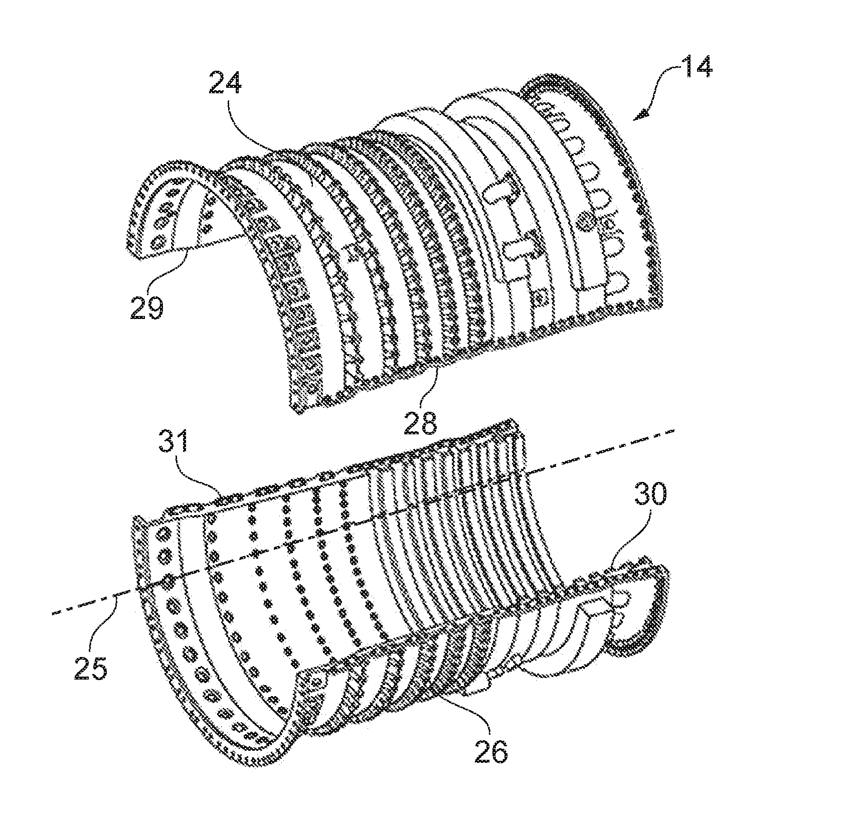
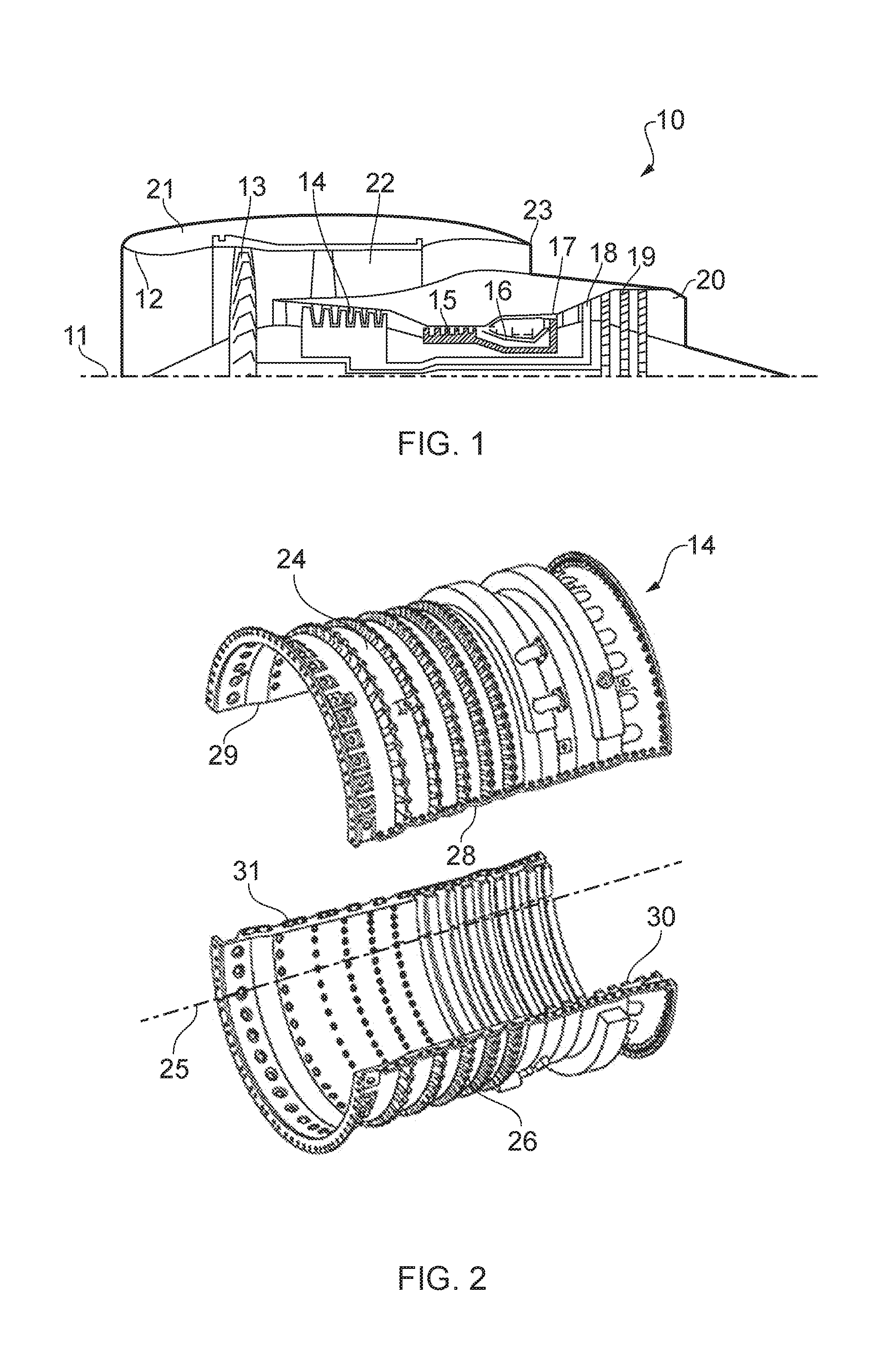
[0066]With reference to FIG. 1, a ducted fan gas turbine engine generally indicated at 10 has a principal and rotational axis 11. The engine 10 comprises, in axial flow series, an air intake 12, a propulsive fan 13, an intermediate pressure compressor (IPC) 14, a high-pressure compressor (HPC) 15, combustion equipment 16, a high-pressure turbine 17, and intermediate pressure turbine 18, a low-pressure turbine 19 and a core engine exhaust nozzle 20. A nacelle 21 generally surrounds the engine 10 and defines the intake 12, a bypass duct 22 and a bypass exhaust nozzle 23.

[0067]The gas turbine engine 10 works in a conventional manner so that air entering the intake 12 is accelerated by the fan 13 to produce two air flows: a first air flow into the intermediate pressure compressor 14 and a second air flow which passes through a bypass duct 22 to provide propulsive thrust. The intermediate pressure compressor 14 compresses the air flow directed into it before delivering that air to the hi...


PUM


Abstract

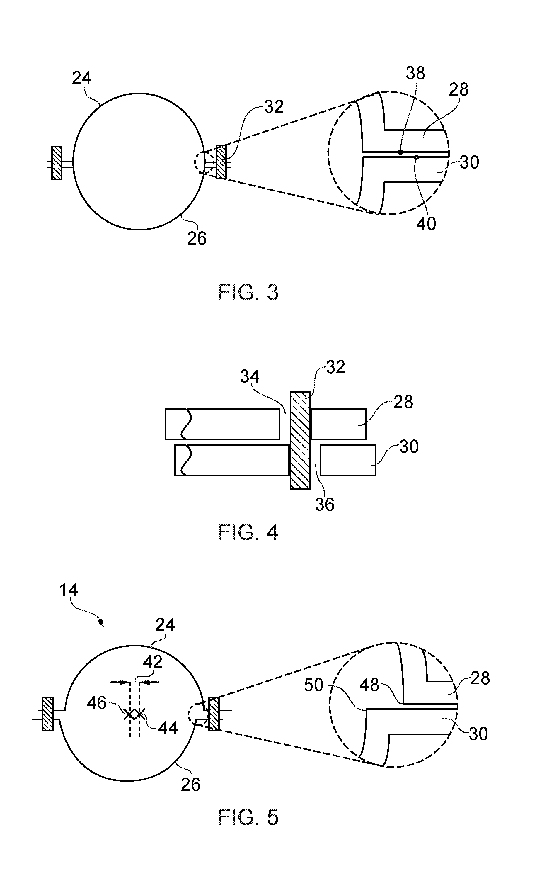
This invention concerns alignment of parts of a multi-part component such as an Intermediate Pressure Compressor (IPC) or High Pressure Compressor (HPC) casing. First and second sections (124,126) of a component (114) are provided with flanges (128,130) having contact surfaces (138,140) provided with corresponding surface profiles formed using smooth radius curves to limit the relative locations of the first and second sections (124,126).

Description

BACKGROUND OF THE INVENTION[0001]The present invention relates to improving alignment between flanged components during assembly, for example improving the alignment of semi-circular split casings or whole circumference stack casings such as those used in the compressor stages of a gas turbine engine.[0002]Gas turbine engines typically employ a multi-stage axial compression system for compression of air passing through the engine. A fan at the front of the engine provides initial low pressure compression, before Intermediate and High Pressure Compressors housed within the body of the engine further increase the pressure to the levels required at the combustor.[0003]For ease of assembly and manufacture, the generally cylindrical Intermediate Pressure Compressor (IPC) within a gas turbine engine is made up of two semi-circular split casing segments which are attached together using bolted flanges.[0004]Typically, the two halves of the split casing structure are bolted together with th...

Claims


Application Information

Patent Timeline
IPC IPC(8): F04D29/52F04D29/08F04D29/64
CPCF04D29/522F04D29/644F05D2230/10F05D2220/32F05D2230/60F04D29/083F01D25/243F05D2230/64F05D2250/184Y02T50/60F05D2200/261F05D2240/14F05D2260/30
Inventor O'TOOLE, JAMES A CHOLT, JAMES
Owner ROLLS ROYCE PLC
Learn More