Dark field flow cytometry imaging system

Inactive Publication Date: 2016-11-24
FLUID IMAGING TECH
View PDF2 Cites 2 Cited by
  • Summary
  • Abstract
  • Description
  • Claims
  • Application Information

AI Technical Summary

Benefits of technology

The present invention provides an improved imaging system and method that can be used in flow cytometers. The improvement is made through dark field analysis, which allows for better particle imaging than bright field imaging. Additionally, the invention modifies the lens of a conventional condenser to have a light diffuser and a blocking aperture with a high numerical aperture, which increases the amount of scattered light collected by the objective. This results in a much better light throughput. Combining this modified lens with a high intensity strobe light allows for quick imaging of scattering particles.

Problems solved by technology

A primary limitation is that the light level in the generated image is very low.
This means the sample must be very strongly illuminated, which can cause damage to the sample.
However, the interpretation of dark field images must be done with great care, as common dark features of bright field microscopy may be invisible, and vice versa.
The difficulties associated with dark field imaging in stationary microscopic observations of samples are stronger in the analysis of images of particles moving in a flowing fluid.
As a result, the use of dark field imaging has heretofore not been contemplated in flow imaging.

Method used


Image

  • Dark field flow cytometry imaging system
  • Dark field flow cytometry imaging system
  • Dark field flow cytometry imaging system

Examples


Embodiment Construction

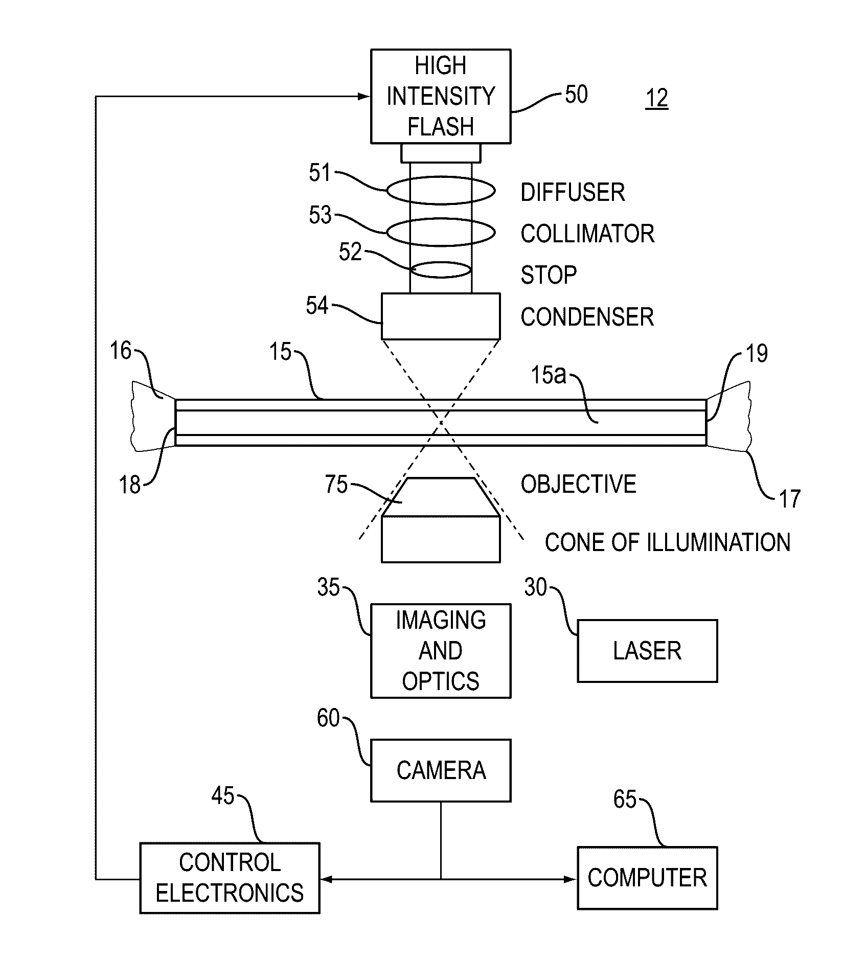
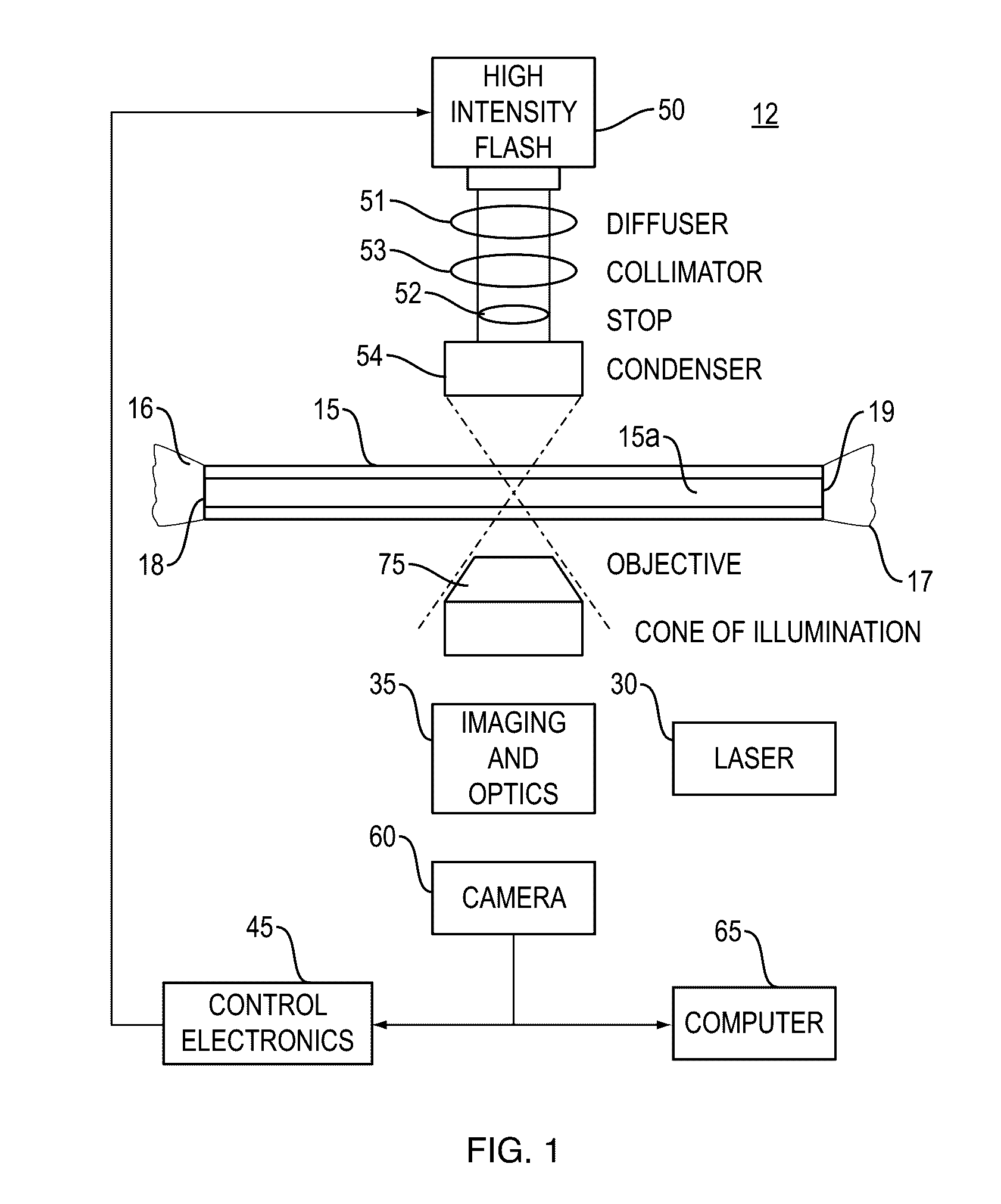
[0018]As illustrated in FIG. 1, a particle imaging system 12 of the present invention includes a flow chamber 15 coupled to an inlet conduit 16 and an outlet conduit 17, a light source 30, an imaging and optics system 35, an image detection system 40 including control electronics 45, a backlighting generator 50, in image capturing system 60 and a computing device 65. The combination of these components of the system 12 arranged and configured as described herein enable a user to detect particles in a sample and, specifically, to enhance the image captured by the system.

[0019]The flow chamber 15 includes an inlet 18 for receiving the particle-containing sample to be evaluated and an outlet 19 through which the sample passes out of the flow chamber 15 after imaging functions have been performed. A pump may be used to move the fluid into the flow chamber 15. The flow chamber 15 may be fabricated of a material suitable for image capturing, including, for example, but not limited to, tra...


PUM


Abstract

An imaging flow cytometry system including dark field illumination to contrast particles in a flowing fluid. The system includes a condenser with blocking aperture and a numerical aperture of no less than 0.4. The system also includes a microscope objective for focusing dark field illuminated particles, wherein the objective has a numerical aperture of 0.3. The system further includes imaging optics, an image capturing system and a backlighting generator.

Description

FIELD OF THE INVENTION[0001]The present invention relates generally to an optical flow imaging and analysis configuration used in particle analysis instrumentation, and more particularly to an optical flow imaging system and method incorporating the imaging technique referred to as dark field imaging in flow particle imaging. This combination provides effective contrast in illuminating particles thereby enabling more effective particle detection and identification than previously enabled.BACKGROUND OF THE INVENTION[0002]Various optical / flow systems employed for transporting a fluid within an analytical instrument to an imaging and optical analysis area exist in the art. A liquid sample is typically delivered into the bore of a flow chamber and the sample is interrogated in some way so as to generate analytical information concerning the nature or properties of the sample. For example, a laser beam may excite the sample present in the bore of the flow cell, and the emitted fluorescen...

Claims


Application Information

Patent Timeline
IPC IPC(8): G01N15/14
CPCG01N15/1436G01N2015/1486G01N15/1456G01N2015/1006G01N15/1434G01N15/147G02B21/10G02B21/36
Inventor SIERACKI, CHRISTIAN K.PETERSON, KENT A.LABRENCIS, ILMARS
Owner FLUID IMAGING TECH
Why Eureka
Try Eureka