
Electrochemical energy conversion devices and cells, and negative electrode-side materials for them

a technology of electrochemical energy conversion device and negative electrode side material, which is applied in the direction of fuel cells, cell components, electrical apparatus, etc., can solve the problems of not always being the case, affecting the performance of the cell in use, and causing damage, so as to prevent the release of poisons and alleviate the sintering of negative electrode material

Active Publication Date: 2016-12-01
CHAOZHOU THREE CIRCLE GRP
View PDF3 Cites 6 Cited by
  • Summary
  • Abstract
  • Description
  • Claims
  • Application Information

AI Technical Summary

Benefits of technology

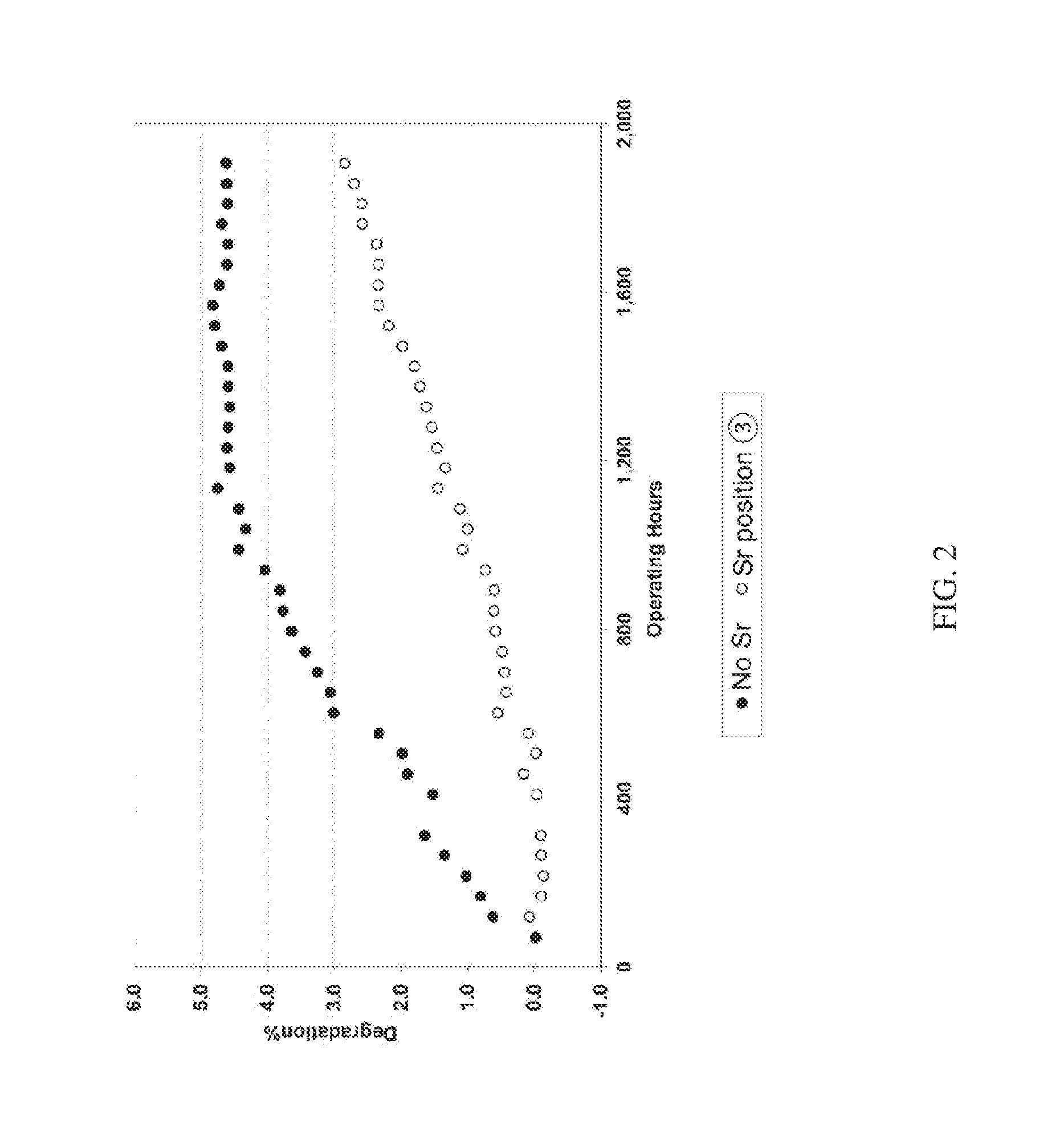
The invention relates to a method for improving the performance and durability of electrochemical energy conversion cells. The method involves using chemically unbound material on the negative electrode side of the cells to reduce degradation of the cell performance during use. The unbound material can act by increasing electrical conductivity or alleviating sintering of the metal in the negative electrode material. An electrochemical energy conversion cell comprising a layer of solid oxide electrolyte and one or more porous layers including a functional layer of negative electrode material and a layer of positive electrode material is also provided. The cells prepared using this method have improved performance and durability.

Problems solved by technology

The poisons may include sulphur species, boron species and phosphorus species, but other species such as chlorine, siloxane and selenium may also be reacting with or otherwise affecting the negative electrode material, or at the electrode / electrolyte interface, and detrimentally affecting the performance of the cell in use.
The element or component of the negative electrode material with which the poisons would be expected to react are the nickel or other metal in a cermet composition, but this may not always be the case.

Method used


Image

  • Electrochemical energy conversion devices and cells, and negative electrode-side materials for them
  • Electrochemical energy conversion devices and cells, and negative electrode-side materials for them
  • Electrochemical energy conversion devices and cells, and negative electrode-side materials for them

Examples


Embodiment Construction

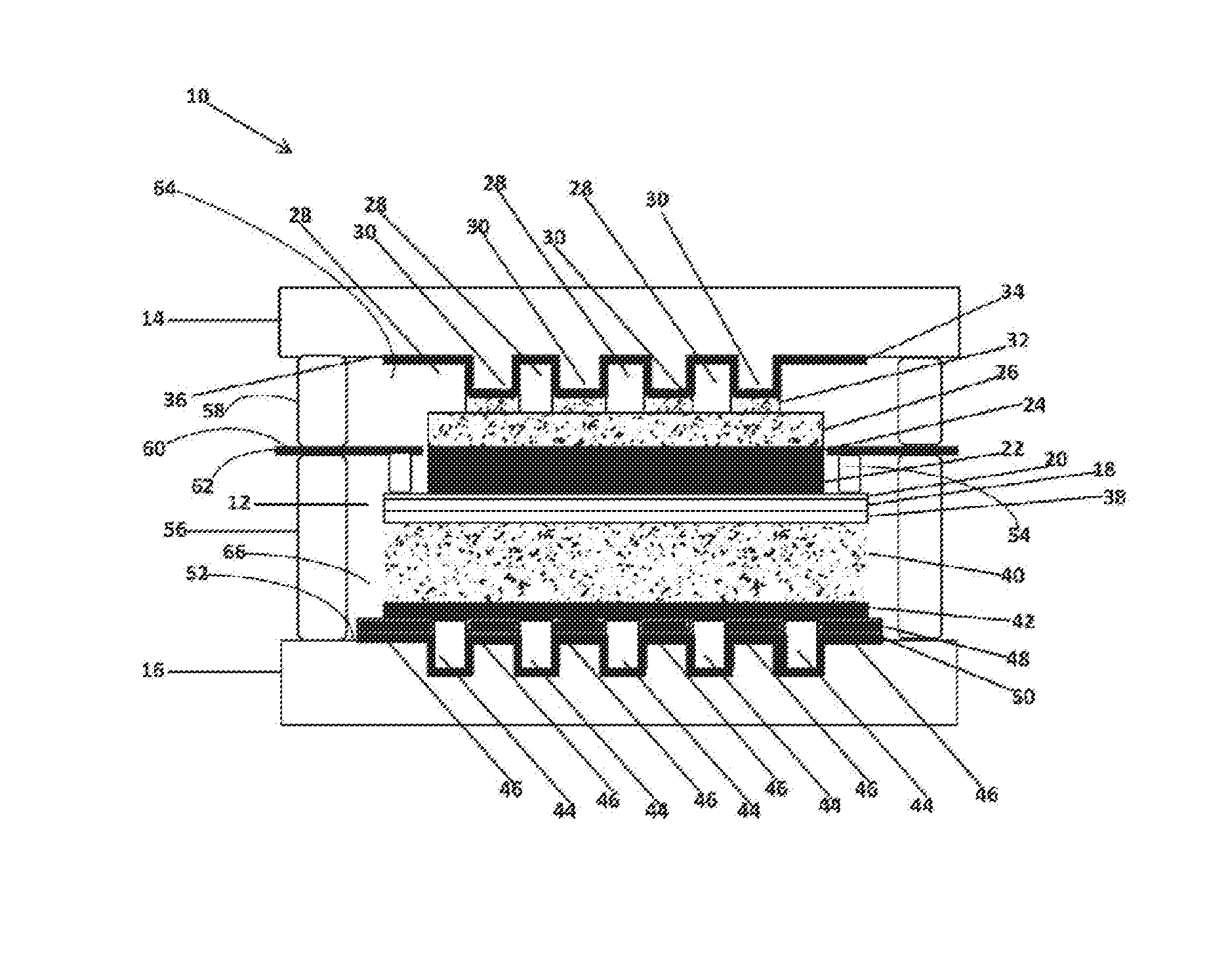
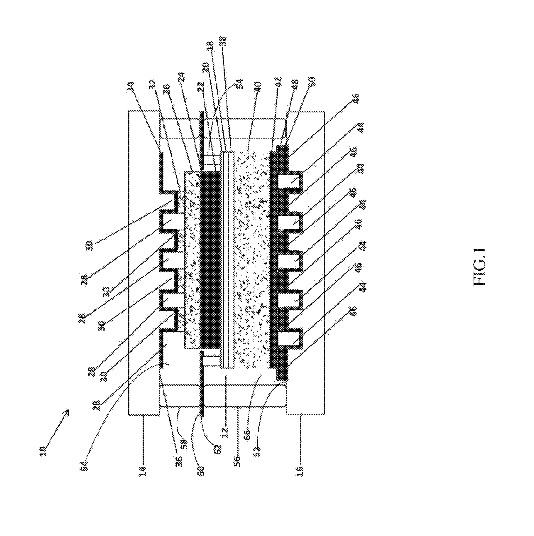
[0090]FIG. 1 is sectional view illustrating a planar fuel cell assembly 10 of the type used to test the present invention. The figure is not to scale and is provided in the form shown for ease of illustration. The assembly 10 comprises a fuel cell unit 12 between opposed interconnect plates 14 and 16. In a commercial fuel cell device, multiples of these assemblies 10 would be stacked on top of each other, with each pair of abutting interconnector plates 14 and 16 being formed as a single plate. As illustrated, the interconnect plate 14 is a positive electrode- or cathode-side interconnect, while the interconnect plate 16 is a negative electrode- or anode-side interconnect. They are formed of chromium-containing high temperature resistant ferritic steel such as Crofer 22HJ Crofer 22APU and ZMG 232L.

[0091]Between the interconnect plates 14 and 16, the fuel cell unit 12 comprises a dense electrolyte layer 18 of 8YSZ having a thickness in the range of 5 to 20 μm, for example 10 μm, with...


PUM


Abstract

An electrochemical energy conversion device 10 comprising a stack of solid oxide electrochemical cells 12 alternating with gas separators 14, 16, wherein scavenger material selected from one or both of free alkali metal oxygen-containing compounds and free alkaline earth metal oxygen-containing compounds is provided in or on one or more of the negative electrode-side of the cell 12, the adjacent gas separator 16 and any other structure of the device 10 forming a gas chamber 66 between the cell and the gas separator. The invention also extends to the treated cell 12.

Description

PRIORITY[0001]This application claims priority from Australian Provisional Patent Applications 2014900069 and 2014900070 each filed on 9 Jan. 2014 (the priority applications), and the entire content and disclosure of each of those provisional patent applications is incorporated herein by reference.TECHNICAL FIELD[0002]The present invention relates to electrochemical energy conversion devices as well as to solid oxide electrochemical cells for them, and is particularly concerned with reducing degradation in the electrochemical performance of the cell s and devices.BACKGROUND ART[0003]Electrochemical energy conversion devices include fuel cell systems as well as hydrogen generators and other electrolysers, such as for co-electrolysing water and CO2.[0004]Fuel cells convert gaseous fuels (such as hydrogen, natural gas and gasified coal) via an electrochemical process directly into electricity. A fuel cell continuously produces power when supplied with fuel and oxidant, normally air. A ...

Claims


Application Information

Patent Timeline
IPC IPC(8): H01M4/86H01M4/90H01M8/2432H01M8/243H01M8/1213H01M8/2435
CPCH01M4/8673H01M8/1213H01M8/2435H01M2008/1293H01M8/243H01M4/9066H01M4/9033H01M8/2432H01M8/0219H01M2004/8684H01M4/8657H01M4/8663Y02E60/50H01M8/2425H01M8/1231
Inventor QIU, JIHUACHEN, SHUOSHUO
Owner CHAOZHOU THREE CIRCLE GRP
Learn More