Ozone water supply method and ozone water supply device

a technology of ozone water supply and water supply device, which is applied in the direction of transportation and packaging, water/sewage treatment by oxidation, non-contaminated water treatment, etc., can solve the problems of easy autodecomposition of ozone in water, unstable substance, etc., and achieve the effect of suppressing or reducing the accumulation of nitric acid

Active Publication Date: 2016-12-15
ORGANO CORP
View PDF4 Cites 20 Cited by
  • Summary
  • Abstract
  • Description
  • Claims
  • Application Information

AI Technical Summary

Benefits of technology

[0024]One aspect of the invention thus provides an ozonated water supply method that feeds ozonated water to the use point while recycling ozonated water that has not been used at the u

Problems solved by technology

Ozone is an unstable substance, and easi

Method used


Image

  • Ozone water supply method and ozone water supply device
  • Ozone water supply method and ozone water supply device
  • Ozone water supply method and ozone water supply device

Examples


example 1

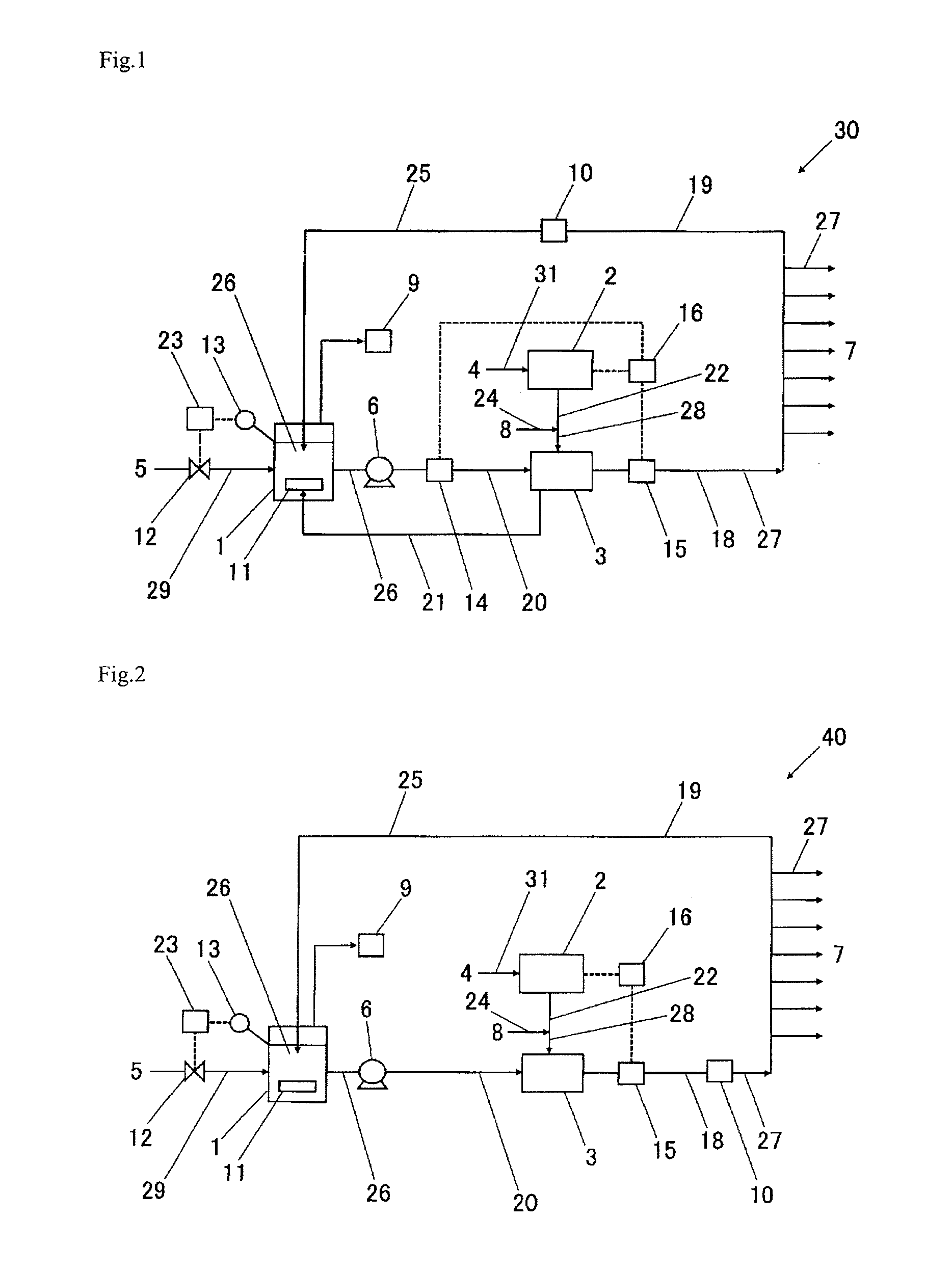
[0084]Ozonated water was supplied in accordance with the flow diagram illustrated in FIG. 2.

[0085]Ultrapure water (feed water) having a specific resistivity of 18 MΩ·cm or more and a TOC content of 1.0 ppb or less was fed to a circulation tank 1 made of PFA. High-purity oxygen gas (feed gas) having a nitrogen gas content of 0.01 vol % was fed to a nitrogen-free-compliant discharge-type ozone gas production device 2 (“GRF-RG” manufactured by Sumitomo Precision Products Co., Ltd.) at 8 SLM (L / min at 0° C., 1 atm) through an oxygen gas feed pipe. Carbon dioxide was added to ozone gas produced by the ozone gas production device 2 at 100 SCCM (mL / min at 0° C., 1 atm), and the mixture was dissolved in the dissolving water using an ozonation membrane 3 made of PTFE. The ozone gas that had not been dissolved using the ozonation membrane was fed to an ozone gas decomposition means.

[0086]The capacity of the circulation tank 1 was controlled to be 40 L using a water feed rate control means (wa...

example 2

[0089]An experiment was performed in the same manner as in Example 1, except that the ozonated water was not used at the use point (i.e., the ozonated water was returned to the circulation tank in a ratio of 100% (i.e., the average use ratio at the use point was 0%)).

[0090]The feed rate of the ozonated water was approximately 30.0 L / min, and the dissolved ozone concentration was approximately 30.0 ppm. The average discharge power of the discharge-type ozone gas production device was 17.4%, and the nitric acid concentration in the ozonated water measured after 2 hours of continuous operation was 5 ppb (minimum limit of determination) or less. The rotational speed of the feed pump was set to 8,500 rpm, and the number of particles (particle size: 0.05 μm or more) included in the ozonated water (at the use point) was 10 or less per mL.

example 3

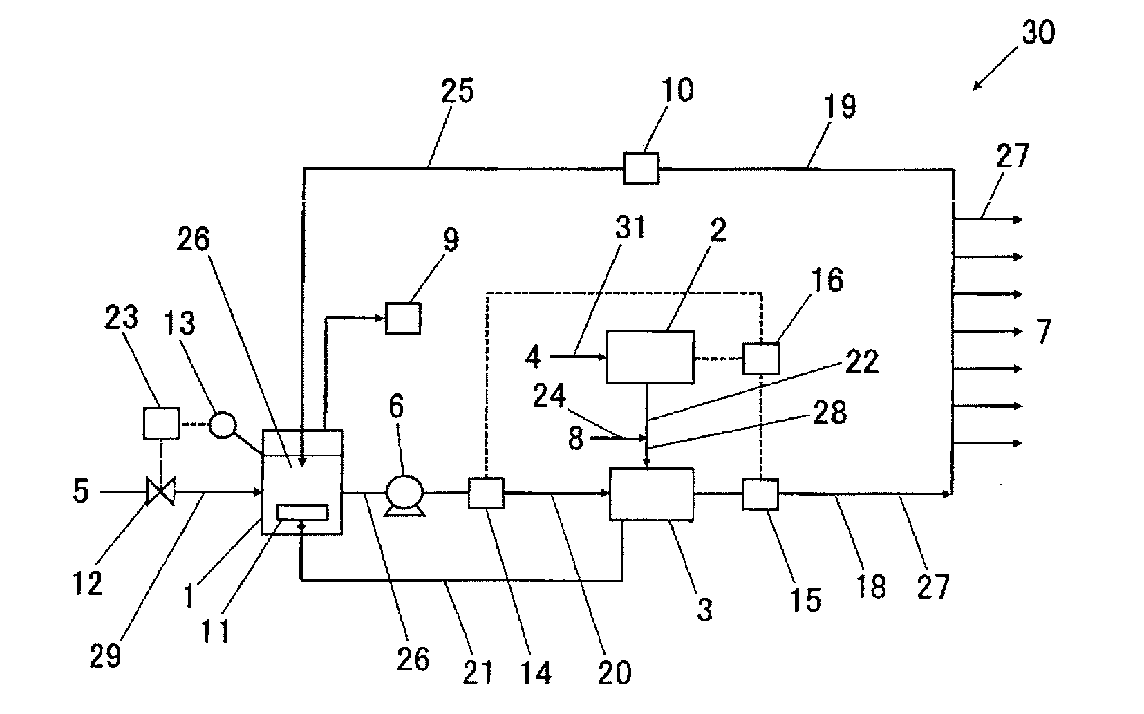
[0091]Ozonated water was supplied in accordance with the flow diagram illustrated in FIG. 1.

[0092]Ultrapure water (feed water) having a specific resistivity of 18 MΩ·cm or more and a TOC content of 1.0 ppb or less was fed to a circulation tank 1 made of PFA. High-purity oxygen gas (feed gas) having a nitrogen gas content of 0.01 vol % was fed to a nitrogen-free-compliant discharge-type ozone gas production device 2 (“GRF-RG” manufactured by Sumitomo Precision Products Co., Ltd.) at 8 SLM (L / min at 0° C., 1 atm) through an oxygen gas feed pipe. Carbon dioxide was added to ozone gas produced by the ozone gas production device 2 at 100 SCCM (mL / min at 0° C., 1 atm), and the mixture was dissolved in the dissolving water using an ozonation membrane 3 made of PTFP. The ozone gas that had not been dissolved using the ozonation membrane was fed to a diffusion section 11 provided inside the circulation tank 1.

[0093]The capacity of the circulation tank 1 was controlled to be 40 L using a wate...


PUM

PropertyMeasurementUnit
Concentrationaaaaaaaaaa

Abstract

An ozonated water supply method includes: feeding dissolving water contained in a circulation tank to an ozonation device at a given feed rate while feeding ultrapure water to the circulation tank, and returning ozonated water that has not been used at a use point to the circulation tank, dissolving ozone in the dissolving water using the ozonation device to obtain ozonated water, and feeding the ozonated water to the use point; feeding oxygen gas having a nitrogen gas content of 0.01 vol % or less to a discharge-type ozone gas-producer, and feeding the resulting ozone-containing gas to the ozonation device; adjusting the feed rate of the ultrapure water to the circulation tank; and adjusting the dissolved ozone concentration in the ozonated water. The method can reduce or suppress the accumulation of nitric acid in the recirculation system when a discharge-type ozone gas-producer is used as the ozone gas-producer.

Description

TECHNICAL FIELD[0001]The present invention relates to an ozonated water supply method and an ozonated water supply device. More specifically, the invention relates to an ozonated water supply method and an ozonated water supply device that recycle ozonated water that has been fed to the use point, but has not been used at the use point.BACKGROUND ART[0002]A semiconductor device (including a liquid crystal display device) production process includes repeatedly performing a cleaning step on a substrate in order to remove an organic substance, particles, and the like that adhere to the surface of the substrate. An organic solvent, an acid solution, and the like are widely used as a cleaning liquid used for the cleaning step. In recent years, ozonated water that rarely causes environmental issues has been used as the cleaning liquid.[0003]Ozonated water used for the semiconductor device production process is required to have a high ozone concentration from the viewpoint of reactivity, a...

Claims


Application Information

Patent Timeline
IPC IPC(8): B01F3/04C01B13/11B01F5/10C02F1/78B01F15/00B01F3/20B01F23/70
CPCB01F3/04985B01F3/04439B01F15/0022B01F3/2057B01F5/106C02F1/78C01B13/11B01F2003/04886C02F2201/782C01B2201/64C01B2201/90C02F2103/04C02F2209/23B01F23/237613B01F23/29B01F25/53B01F35/2132B01F35/2211B01F35/82B01F23/708B01F23/2319
Inventor HAYASHI, YOSHIFUMIYAMASHITA, YUKINARIYAMANAKA, KOJI
Owner ORGANO CORP
Why Eureka
Try Eureka