Dual-solvent extraction of oil sand bitumen

a technology of oil sand bitumen and solvent, which is applied in the petroleum industry, liquid hydrocarbon mixture production, etc., can solve the problems of economic losses and environmental problems, fire hazards caused by the use of light or intermediate solvents, and recoveries of bitumen, so as to optimize the recovery and separation rate of bitumen, and improve safety.

Inactive Publication Date: 2016-12-15
SYNCRUDE CANADA LTD
View PDF4 Cites 1 Cited by
  • Summary
  • Abstract
  • Description
  • Claims
  • Application Information

AI Technical Summary

Benefits of technology

[0014](1) The solvent extraction process of the present invention provides greater flexibility in the choices of heavy solvent (HS) and light solvent (LS), and the ranges of HS / LS mass ratios. The HS / LS mass ratio may vary from the first to the last separation stage within the process to optimize bitumen recovery and separation rate.
[0015](2) The process improves safety and minimizes solvent vapor loss. After initial contact with a high-flash point HS to form dense slurry for oil sand deoxygenation and before mixing with LS and solids flocculation, the dense slurry is passed through an airlock to isolate oxygen-free and LS-containing atmosphere downstream from oxygen-containing and LS-free atmosphere upstream, thereby reducing fire hazard or solvent loss.

Problems solved by technology

Part of the wet tailings becomes fluid fine tailings (FFT), which contain approximately 30% fine solids and are a great challenge for tailings treatment.
In addition, certain “problem” oil sands, often having high fines content, yield low bitumen recoveries in the water-based extraction process.
This leads to economic losses and environmental issues with bitumen in wet tailings.
This solvent may be a light solvent with a typical boiling range of 36-110° C., an intermediate solvent with a typical boiling range of 66-205° C., or a heavy solvent with a typical boiling range of 177-343° C. However, the use of any light or intermediate solvent poses a fire hazard during the initial contact of solvent with oil sands in a vessel that is not adequately purged or deoxygenated with an inert gas.
Effectively purging such a vessel is a challenge due to the sticky nature of oil sands that may not allow effective use of air locks for the feed.
If the oil sands are transported from a deoxygenation unit to a solvent contact unit through a semi-open port, solvent vapor may travel from the solvent contact unit to the deoxygenation unit and mix with air and / or the inert gas, thereby posing a fire hazard and causing solvent loss.
However, this process may add excessive water which is problematic for solvent recovery.
Attempts to solve the above issues by using two solvents sequentially encounter solid / liquid separation problems and issues with higher solvent demand and operating costs.
The second stream cannot be directly recycled at the initial slurry preparation stage due to the presence of the second (volatile) solvent and the safety / solvent loss issues mentioned above.
These two streams necessitates two separate flash / distillation units for separation, complicating the process and incurring greater operational costs compared to a single-solvent extraction process which allows direct recycling of low bitumen streams at the slurry preparation stage and requires only one flash / distillation unit for its product.
Combining these two streams as in U.S. Pat. No. 3,117,922 reduces the bitumen concentration in the product and increases the size and cost of the flash / distillation unit to process the diluted product.
Drying the relatively wet agglomerates using multiple dryers is an energy-intensive, uneconomical operation.
In summary, none of the prior art solvent extraction processes can resolve all of the following issues:1. Fire hazard and solvent loss at initial contact of solvent with oil sands in an extraction process using a single volatile solvent;2. Complicated flow sheet and greater operational costs for multiple flash / distillation units in an extraction process using two solvents; and3. Conflicting requirements of water addition to satisfy fast solid-liquid separation and drying of spent solids for solvent recovery.

Method used


Image

  • Dual-solvent extraction of oil sand bitumen
  • Dual-solvent extraction of oil sand bitumen
  • Dual-solvent extraction of oil sand bitumen

Examples


example 1

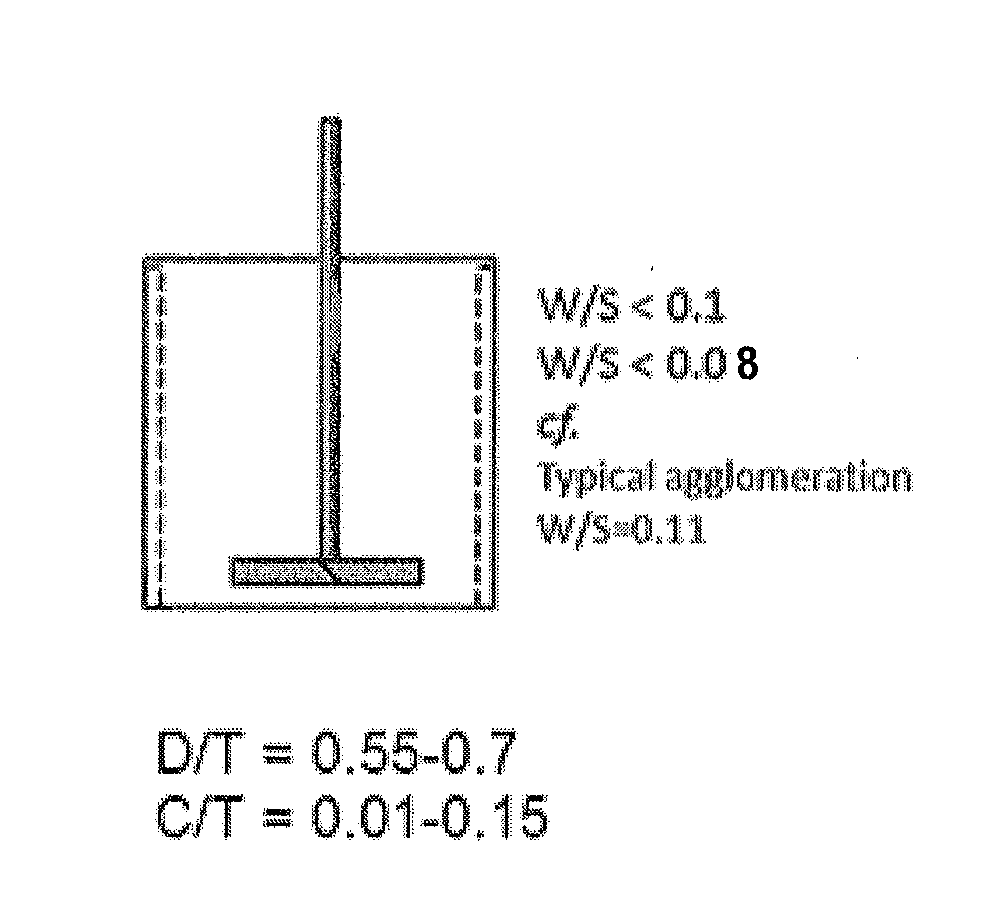
[0069]Table 1 shows the relationship of water-to-solids mass ratios (W / S) in slurry and filtration rates for a test oil sand (#1) containing 9.3 wt % bitumen, 2.1 wt % water and 88.6 wt % solids. The fines (<44 μm) content in the solids was 21 wt %. This oil sand was relatively dry, so by varying the water dosage, the W / S could be adjusted in a wider range. The hydrocarbon phase in the slurry prior to the first filtration step comprised about 30 wt % bitumen, 35 wt % virgin light gas oil and 35 wt % heptane. The solids content in the slurry was about 58 wt %. The solids were flocculated in a baffled dished-bottom mixing tank of 13 cm in diameter (T) at 50° C. The impeller was a 6-blade 45° PBT of 7.6 cm in diameter (D). The bottom clearance (C) was about 1.5 cm. Thus, D / T=0.58 and C / T=0.12. The down-pumping axial impeller was operated at 600 rpm for 4 minutes, providing a power input of about 6 W / kg of slurry. The mixed slurry was transferred to a top-loading batch filter with about...

example 2

[0071]Two samples of oil sands #1 and #2 having 9.3 wt % and 9.7 wt % bitumen, 2.1 wt % and 6.2 wt % water and 21% and 28% fines in solids, respectively, were extracted with dual solvents under similar conditions as described in Example 1. The test for oil sand #2 had zero water addition. Oil sand connate water was the sole source of water for solids flocculation. Both samples went through four stages of filtration with repulping between stages 2 and 3. The filter cake thickness was kept around 4.3 cm. All wash liquids were prepared based on their compositions and flow rates in a continuous process. Table 2 shows the extraction performance.

TABLE 2Initial FiltrateFilter ProcessBitumenW / S MassFluxRateRecovery*Ratio inOil sand(L / m2 s)(t / m2 h)(%)Slurry#15.97.096.90.052#211.18.594.10.074*Bitumen recovery here includes small loss of HS to spent solids that can be deducted from the product bitumen in distillation as HS makeup.

[0072]The bitumen recoveries for oil sands #1 and #2 in water-ba...

example 3

[0073]Tests were conducted to compare the filter process rates and bitumen recoveries achieved using a solids agglomeration method of the prior art which involved a drum agglomerator verses the solids flocculation method of the present invention which involved the mixing tank / impeller described in Example 1, The two solvents used in extraction and the slurry compositions were identical in these two tests and similar to those in Example 1. An oil sand (#3) used in both tests contained about 10 wt % bitumen, 5 wt % water and 85 wt % solids. The fines (<44 μm) content in the solids was 28 wt %. The solids contents in the slurry for the agglomeration and flocculation tests were about 45 wt % and 52 wt %, respectively. The filter cake thicknesses used in the agglomeration and flocculation tests were 10.2 cm and 4.7 cm, respectively. The agglomeration data have been converted based on a hypothetical filter cake thickness of 4.7 cm to be comparable with the flocculation data. Table 3 shows...


PUM

PropertyMeasurementUnit
mass ratioaaaaaaaaaa
wt %aaaaaaaaaa
mass ratioaaaaaaaaaa

Abstract

A process for extracting bitumen from oil sand is provided, comprising: contacting mined oil sand with a high-flash point heavy solvent (HS) to produce a dense oil sand slurry; mixing the dense slurry with a first light solvent (LS) stream and a second LS stream to give a heavy solvent to light solvent (HS/LS) mass ratio of about 75/25 to about 40/60; subjecting the HS/LS-diluted oil sand slurry to a first stage solid-liquid separation to produce a first liquids stream containing bitumen and a first solids stream; and washing the first solids stream with a mixed solvent having a HS/LS mass ratio of about 50/50 to about 20/80 and subjecting the solids and the mixed solvent to a second stage solid-liquid separation to produce a second liquids stream and a second solids stream.

Description

FIELD OF THE INVENTION[0001]The present invention relates to a solvent extraction process which uses at least two different solvents for extracting bitumen from mined oil sands.BACKGROUND OF THE INVENTION[0002]The present commercial bitumen extraction process for mined oil sands is Clark hot water extraction technology or its variants that use large amounts of water and generate a great quantity of wet tailings. Part of the wet tailings becomes fluid fine tailings (FFT), which contain approximately 30% fine solids and are a great challenge for tailings treatment. In addition, certain “problem” oil sands, often having high fines content, yield low bitumen recoveries in the water-based extraction process. This leads to economic losses and environmental issues with bitumen in wet tailings.[0003]An alternative to water-based extraction is solvent extraction of bitumen from mined oil sands, which uses little or no water, generates no wet tailings, and can potentially achieve higher bitum...

Claims


Application Information

Patent Timeline
Patent Type & Authority Applications(United States)
IPC IPC(8): C10G1/04
CPCC10G1/045C10G1/04C10G1/047
Inventor WU XIN ALEXBHATTACHARYA SUJIT
Owner SYNCRUDE CANADA LTD
Why Eureka
Try Eureka