
Copper alloy for electronic and electrical equipment, copper alloy thin sheet for electronic and electrical equipment, and conductive component for electronic and electrical equipment, terminal

a technology of electronic and electrical equipment and conductive components, applied in the direction of superimposed coating process, conductors, transportation and packaging, etc., can solve the problems of difficult to sufficiently and reliably improve stress relaxation resistance, and difficult to achieve excellent stress relaxation resistance and excellent strength and bending formability. , the effect of excellent stress relaxation resistan

Active Publication Date: 2016-12-22
MITSUBISHI MATERIALS CORP +1
View PDF1 Cites 4 Cited by
  • Summary
  • Abstract
  • Description
  • Claims
  • Application Information

AI Technical Summary

Benefits of technology

The invention is a copper alloy that is great for use in electronic and electrical equipment. It has excellent resistance to stress relaxation and is strong and bendable. The alloy can be made into a thin sheet for use in these applications, and can also be used to make conductive parts and terminals.

Problems solved by technology

However, in Patent Documents 1 and 2, the amounts of Ni, Fe, and P were merely considered and it was difficult to reliably and sufficiently improve stress relaxation resistance by only adjusting the amounts thereof.
In addition, Patent Document 3 discloses the adjustment of the ratio Ni / Sn, but there was no consideration of a relationship between a P compound and stress relaxation resistance and it was difficult to sufficiently and reliably improve stress relaxation resistance.
Further, in Patent Document 4, the total amount of Fe, Ni, and P and the atomic ratio (Fe+Ni) / P were merely adjusted, and it was difficult to sufficiently improve the stress relaxation resistance.
As described above, it was difficult to sufficiently improve stress relaxation resistance of the Cu—Zn Sn based alloy by the method proposed in the related art.
Accordingly, in the connector having the structure described above, residual stress is alleviated over time or in a high temperature environment; and thereby, a contact pressure against a conductive member of a partner side is not maintained, and a problem such as contact failure may occur early.
In order to avoid such a problem, there was no choice in the related art but to increase a thickness of a material, and this caused an increase in the cost of a material and an increase in weight.

Method used

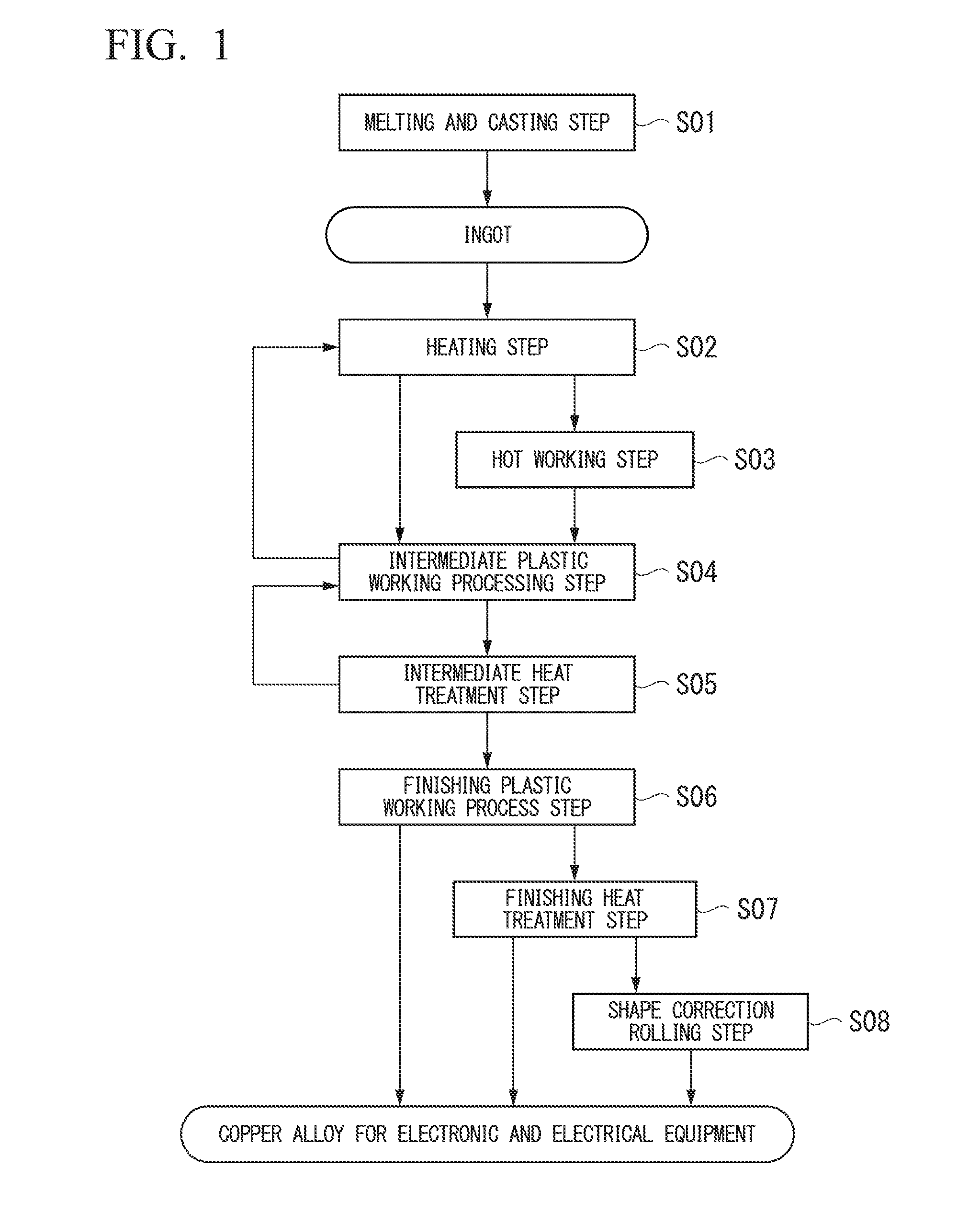

Image

  • Copper alloy for electronic and electrical equipment, copper alloy thin sheet for electronic and electrical equipment, and conductive component for electronic and electrical equipment, terminal

Examples


examples

[0132]Hereinafter, results of confirmatory experiments performed for confirming the effects of the invention will be described as examples of the invention with comparative examples. The following examples are provided to show the effects of the invention, and configurations, processes, and conditions disclosed in the examples do not limit the technical features of the invention.

[0133]First, a raw material consisting of a Cu-40 mass % Zn base alloy and oxygen-free copper (ASTM B152 C10100) having purity of 99.99% or more was prepared, and this raw material was charged in a high-purity graphite crucible and melted in a N2 gas atmosphere using an electric furnace. Various additive elements were added into a molten copper alloy to prepare molten alloys having component compositions shown in Tables 1 to 4, and each of the resultant molten alloys was poured in a carbon mold to produce an ingot. Regarding a size of the ingot, the thickness was set to be approximately 30 mm, the width was ...


PUM

PropertyMeasurementUnit
bending formabilityaaaaaaaaaa
grain sizeaaaaaaaaaa
surface areaaaaaaaaaaa

Abstract

One aspect of this copper alloy for an electronic and electrical equipment contains: more than 2.0 mass % to 36.5 mass % of Zn; 0.10 mass % to 0.90 mass % of Sn; 0.15 mass % to less than 1.00 mass % of Ni; and 0.005 mass % to 0.100 mass % of P, with the balance containing Cu and inevitable impurities, wherein atomic ratios of amounts of elements satisfy 3.00<Ni / P<100.00 and 0.10<Sn / Ni<2.90, and a strength ratio TSTD / TSLD of tensile strength TSTD in a direction perpendicular to a rolling direction to tensile strength TSLD in a direction parallel to the rolling direction exceeds 1.09.

Description

CROSS-REFERENCE TO RELATED PATENT APPLICATIONS[0001]This application is a U.S. National Phase application under 35 U.S.C. §371 of International Patent Application No. PCT / JP2014 / 054042, filed Feb. 20, 2014, and claims the benefit of Japanese Patent Applications No. 2013-145007, filed Jul. 10, 2013 and No. 2013-273548, filed Dec. 27, 2013, all of which are incorporated herein by reference in their entireties. The International application was published in Japanese on Jan. 15, 2015 as International Publication No. WO / 2015 / 004939 under PCT Article 21(2).FIELD OF THE INVENTION[0002]The present invention relates to a Cu—Zn—Sn based copper alloy for electronic and electrical equipment used as a conductive component (conductive part) for electronic and electrical equipment such as a connector of a semiconductor device or other terminals, movable conductive piece of an electromagnetic relay, a lead frame, or the like, a copper alloy thin sheet for electronic and electrical equipment using t...

Claims


Application Information

Patent Timeline
Patent Type & Authority Applications(United States)
IPC IPC(8): C22C9/04H01B1/02B22D7/00C23C30/00C22F1/08C22C1/02
CPCC22C9/04C22F1/08H01B1/026B22D7/005C23C30/005C22C1/02C22F1/00C23C28/02C23C28/021C23C28/023C23C30/00Y10T428/12431Y10T428/12438Y10T428/12708Y10T428/12715Y10T428/12882Y10T428/12903Y10T428/1291Y10T428/263Y10T428/264Y10T428/265
Inventor MAKI, KAZUNARIMORI, HIROYUKIYAMASHITA, DAIKI
Owner MITSUBISHI MATERIALS CORP
Learn More