
Device for generating large volumes of smoke

a smoke generator and large-volume technology, applied in the field of aerosol generation, can solve the problems of limited operational capacity of smoke generators, limited heat storage capacity of gas fired heat sources, and relatively short bursts used, and achieve the effect of increasing heat retention

Inactive Publication Date: 2016-12-22
BATTS PH D FELIX M
View PDF1 Cites 5 Cited by
  • Summary
  • Abstract
  • Description
  • Claims
  • Application Information

AI Technical Summary

Benefits of technology

This patent describes a device that can continuously fire and vaporize a smoke solution. By venting the ignition chamber and using a spark capture tube, ignition is ensured on the first try. The device is self-contained and maintenance-free, and can be used with external nitrogen propellant or fuel. Additionally, the device includes a high-pressured chemical spray cannon. The stainless steel coil allows for continuous firing, and the vaporization of the smoke solution is improved by using a second heater wrapped around the coil. The technical effects of this device include improved efficiency, reliability, and reduced downtime between bursts.

Problems solved by technology

Because the vaporization of the smoke producing liquid drains heat energy from the heat source, the problem that exists with these devices is that they can only be used for relatively short bursts since heating the liquid also cools the heat source.
This is especially true with battery operated heat sources, and even gas fired heat sources have limited capacity to heat before cooling after a smoke burst.
In addition, smoke generators typically have limited operational capacity for smoke producing liquid prior to replacing the source or refilling them with additional fluid.
The device has limited capacity for gas generating liquid and is only operable for short bursts before cooling below the vaporization temperature of smoke producing liquids, since the heat chamber cools very quickly.
In addition, the device cannot generate a dense, thick cloud of smoke as is necessary for many industrial uses.
A further problem with this, and other devices where an ignition spark ignites a gas, is that ignition is very haphazard and igniting the gas can take several tries, leading to a dangerous explosive situation if too much gas accumulates in the ignition chamber before the gases ignite.
One problem of particular note, that has been a weakness for decades for smoke machines, is that the vaporization of the smoke solution and heating the ignition chamber is accomplished by the same propane source.

Method used


Image

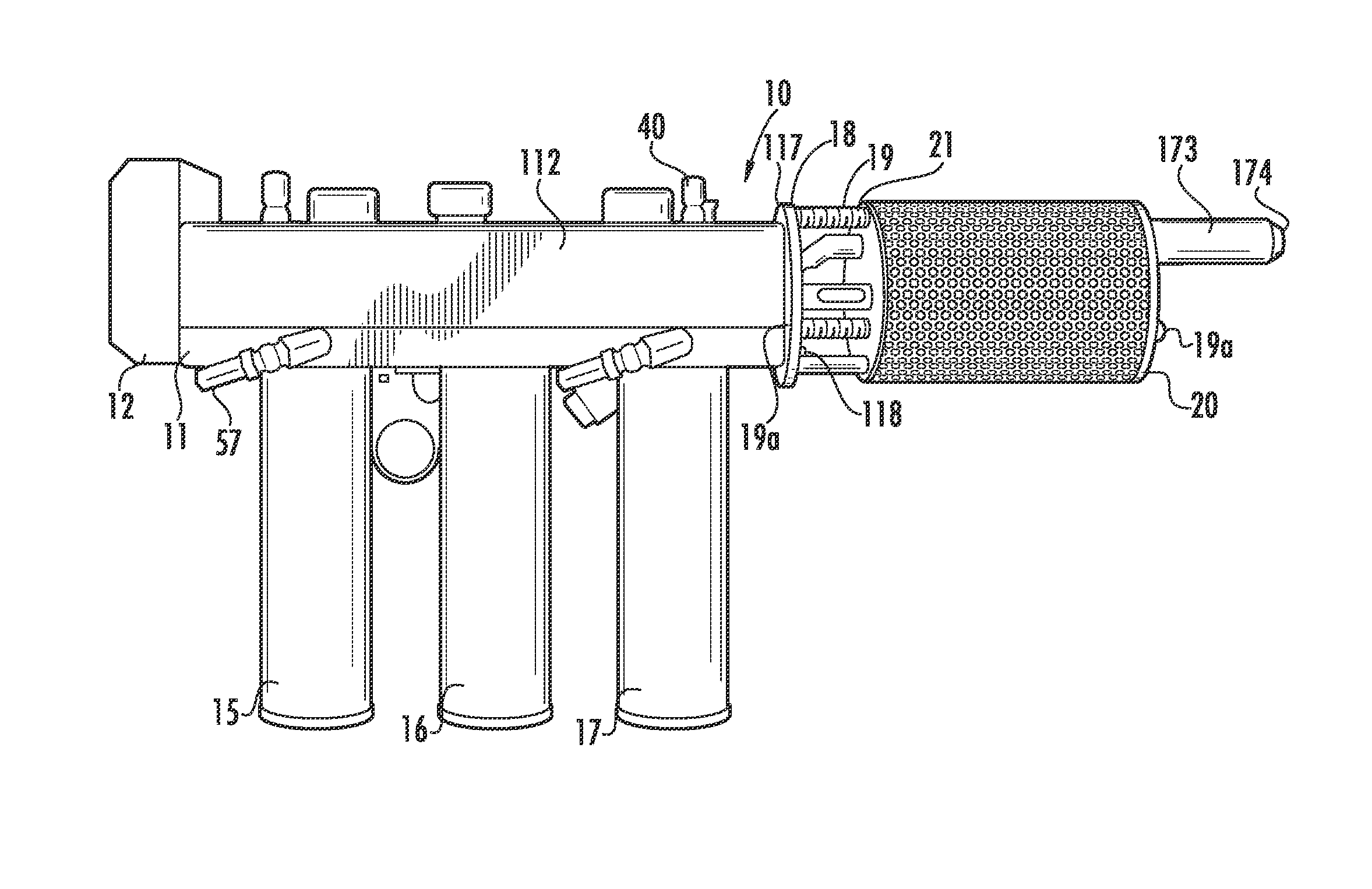
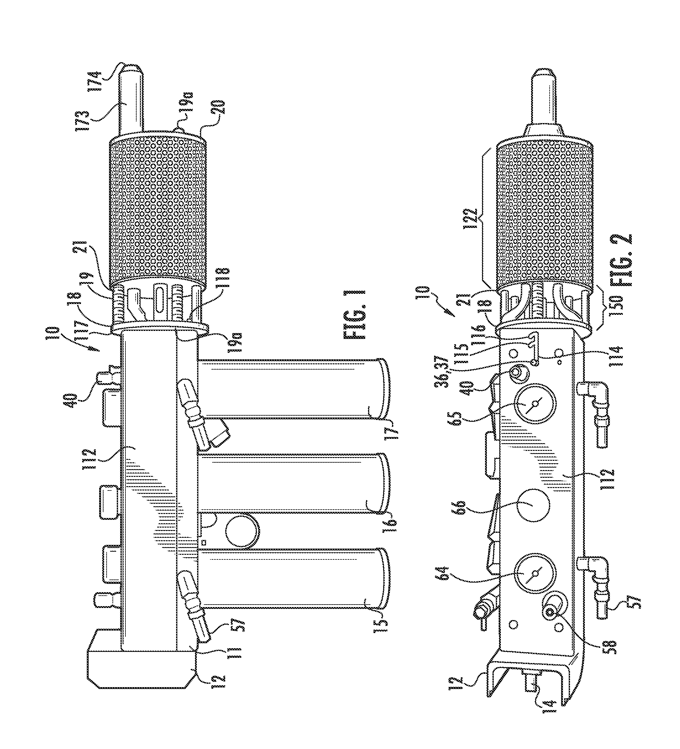
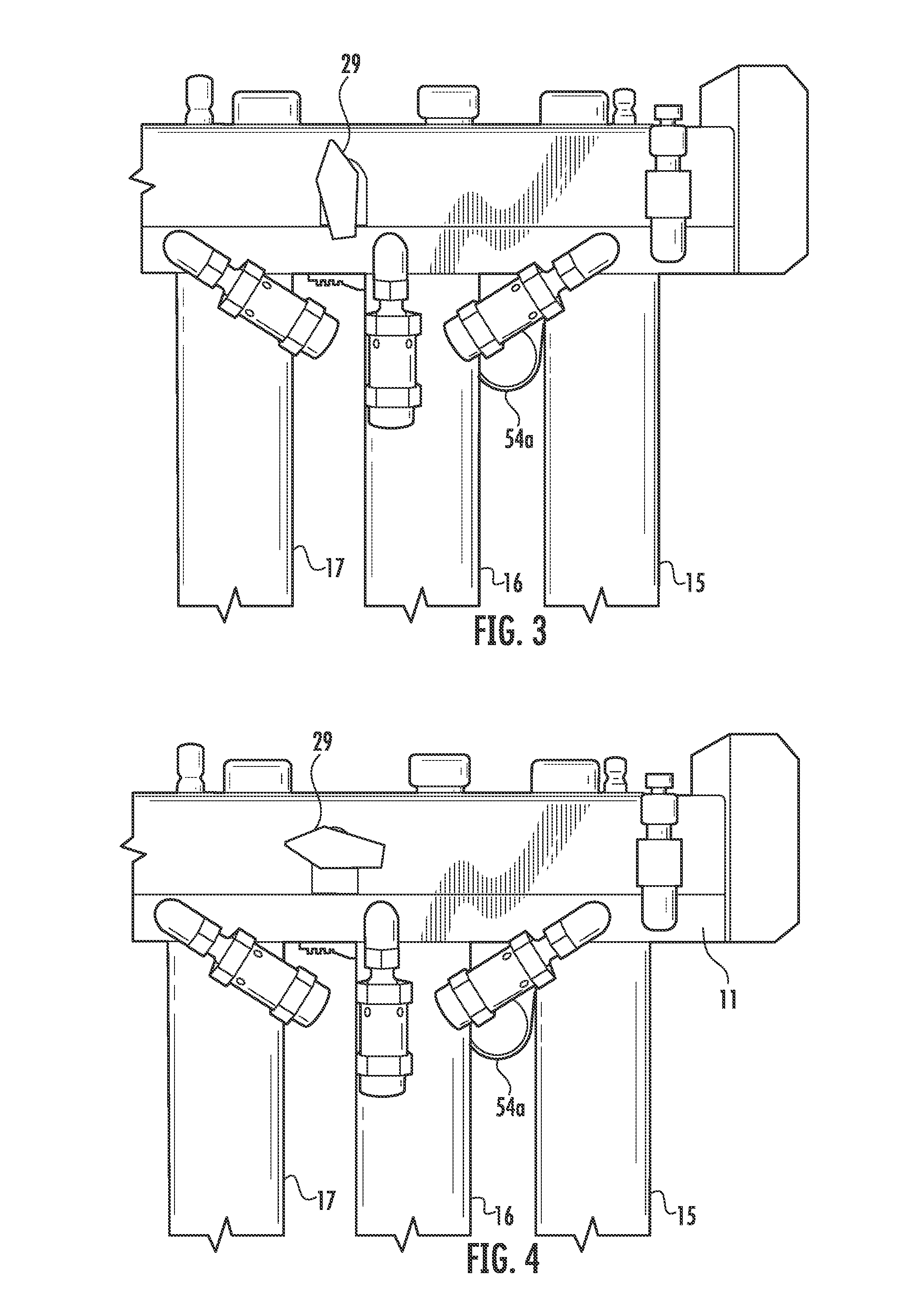
  • Device for generating large volumes of smoke
  • Device for generating large volumes of smoke
  • Device for generating large volumes of smoke

Examples


Embodiment Construction

[0042]While this invention is susceptible to embodiment in many different forms, there is shown in the drawings, and will herein be described in detail, specific embodiments, with the understanding that the present disclosure of such embodiments is to be considered as an example of the principles and not intended to limit the invention to the specific embodiments shown and described. In the description below, like reference numerals are used to describe the same, similar or corresponding parts in the several views of the drawings. This detailed description defines the meaning of the terms used herein and specifically describes embodiments, in order for those skilled in the art to practice the invention.

Definitions

[0043]The terms “a” or “an”, as used herein, are defined as one or as more than one. The term “plurality”, as used herein, is defined as two or as more than two. The term “another”, as used herein, is defined as at least a second or more. The terms “including” and / or “havin...


PUM


Abstract

The present invention relates to a hand held device for continuously producing large volumes of smoke from a smoke producing solution. The design allows for repeated, fast, and lengthy heating of the heating chamber, for use of a duel heating system using a fuel and a heating element wrapped fuel coil for producing continuous use, and thus is an improvement over prior devices which can only be utilized in short bursts.

Description

COPYRIGHT NOTICE[0001]A portion of the disclosure of this patent contains material that is subject to copyright protection. The copyright owner has no objection to the reproduction by anyone of the patent document or the patent disclosure as it appears in the Patent and Trademark Office patent files or records, but otherwise reserves all copyright rights whatsoever.BACKGROUND OF THE INVENTIONField of the Invention[0002]The present invention relates to aerosol generation and, in particular, to a device that is useful for the production of high volumes of non-toxic simulated smoke for industrial use, military use, and the like.Description of Related Art[0003]The generation of a synthetic smoke has been used by the military during combat and training exercises. In addition, it is used by fire departments and police departments for their needs. On the industrial side, theater and motion picture companies frequently use synthetic smoke to simulate smoke for special effects. Typically, th...

Claims


Application Information

Patent Timeline
IPC IPC(8): F41H9/06
CPCF41H9/06A63J5/025
Inventor BATTS PH.D, FELIX M.
Owner BATTS PH D FELIX M
Learn More