Polarisation device for a satellite telecommunications antenna and associated antenna

a technology of polarisation device and satellite telecommunications antenna, which is applied in the direction of electrical apparatus, antenna adaptation in movable bodies, structural forms of radiating elements, etc., to achieve the effect of improving the coupling of polarizing devi

Active Publication Date: 2016-12-22
INEO DEFENSE
View PDF2 Cites 8 Cited by
  • Summary
  • Abstract
  • Description
  • Claims
  • Application Information

AI Technical Summary

Benefits of technology

[0017]According to one embodiment, the device includes at least one dielectric layer

Problems solved by technology

The main drawback of this structure arises from the fact that the distribution of power

Method used


Image

  • Polarisation device for a satellite telecommunications antenna and associated antenna
  • Polarisation device for a satellite telecommunications antenna and associated antenna
  • Polarisation device for a satellite telecommunications antenna and associated antenna

Examples


Embodiment Construction

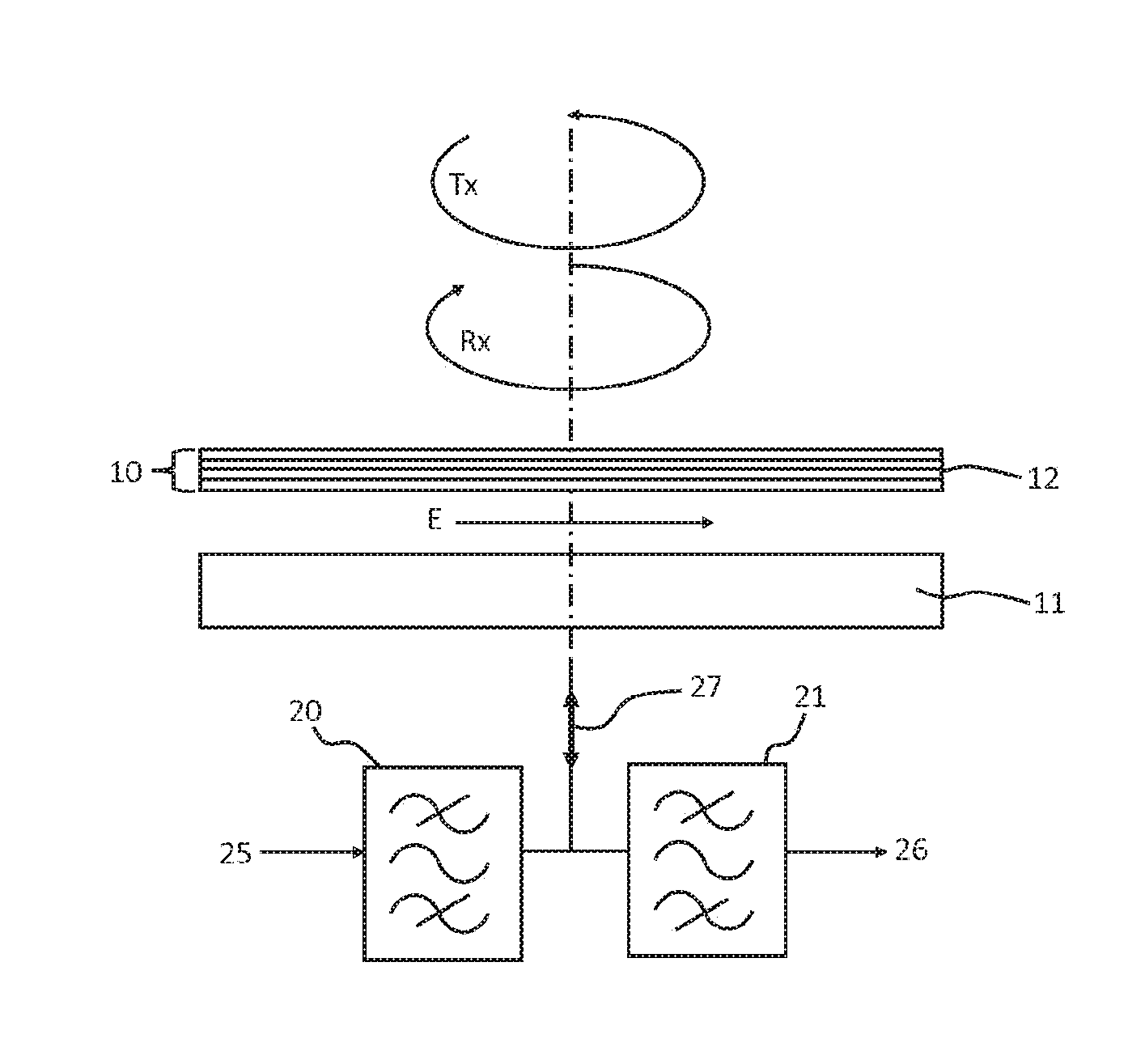
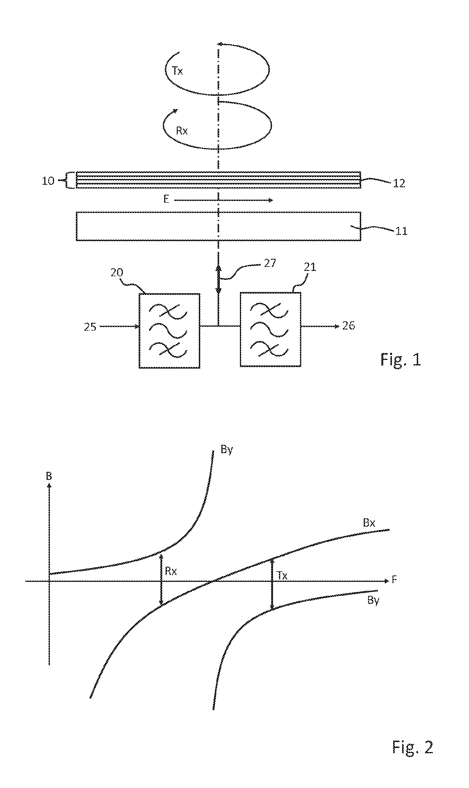
[0028]FIG. 1 shows a panel satellite telecommunications antenna 11 covered with a polarizing device 10 comprising a plurality of frequency-selective layers 12 according to one embodiment of the invention. The satellite telecommunications antenna 11 is connected to a transmission channel 27 able to transmit information in both link directions. When the satellite telecommunications antenna 11 is used to emit, in the emission first frequency band Tx, the signal 25 to be emitted is applied to the input of the Tx filter 20 then transmitted to the antenna 11 via the transmission channel 27. When the antenna 11 is used to receive, in the reception second frequency band Rx, the satellite telecommunications antenna 11 captures a raw signal that is directed over the transmission channel 27 to the Rx filter 21 in order to be oriented toward the receiver 26. The Rx and Tx filters 21, 20, together form a diplexer.

[0029]A linear polarization E emitted by the antenna 11 may be decomposed into two ...


PUM


Abstract

The present invention relates to a polarisation device (10) for a satellite telecommunications antenna (11) including at least one frequency selective layer (12) able to convert a linear polarisation (E), including two components (Ex, Ey), into left circular polarisation in a first transmission frequency band (Tx) and into right circular polarisation in a second receiving frequency band (Rx) or vice versa, the phase shift between the two components (Ex, Ey) of the linear polarisation (E) being included between −85 and −95 degrees, preferably −90 degrees in one of the frequency bands (Rx, Tx), and the phase shift between the two components (Ex, Ey) of the linear polarisation (E) being included between +85 and +95 degrees, preferably +90 degrees in the other frequency band (Rx, Tx).

Description

FIELD OF THE INVENTION[0001]The present invention relates to the field of polarizers for satellite telecommunications antennae. The invention also relates to an associated satellite telecommunications antenna.[0002]The invention is in particular advantageously applicable to the emission and reception of data to or from a satellite especially for satcom (acronym of satellite communications) type satellite telecommunications.PRIOR ART[0003]Satellite telecommunications conventionally use an emission frequency band Tx and a reception frequency band Rx. The emission and reception polarizations are often both circular but of opposite handedness, especially for certain satellites working in the X, Ka and Q / V bands.[0004]The use of circular polarization is particularly well adapted to communications between a moving platform (terrestrial vehicle, naval vessel, plane, etc.) and a satellite because, in contrast to linear polarization, it is not necessary to orient the polarization.[0005]Produ...

Claims


Application Information

Patent Timeline
IPC IPC(8): H01Q1/28H01Q15/00H01Q1/38H01Q15/24
CPCH01Q1/288H01Q1/38H01Q15/006H01Q15/244H01Q15/0026
Inventor COLLIGNON, GERARD
Owner INEO DEFENSE
Why Eureka
Try Eureka