
Passive two-phase cooling circuit

Active Publication Date: 2016-12-29
FRAMATOME GMBH
View PDF5 Cites 1 Cited by
  • Summary
  • Abstract
  • Description
  • Claims
  • Application Information

AI Technical Summary

Benefits of technology

The invention is a new type of cooling system that solves problems with existing systems. It is simple and cheap to make, and it reduces or eliminates pressure shocks during operation.

Problems solved by technology

In addition, by using the liquid column, pressure is reduced at the output of the condenser, resulting in an increase in the driving pressure difference in the condenser and thus in an increased mass flow rate.

Method used


Image

  • Passive two-phase cooling circuit
  • Passive two-phase cooling circuit
  • Passive two-phase cooling circuit

Examples


Embodiment Construction

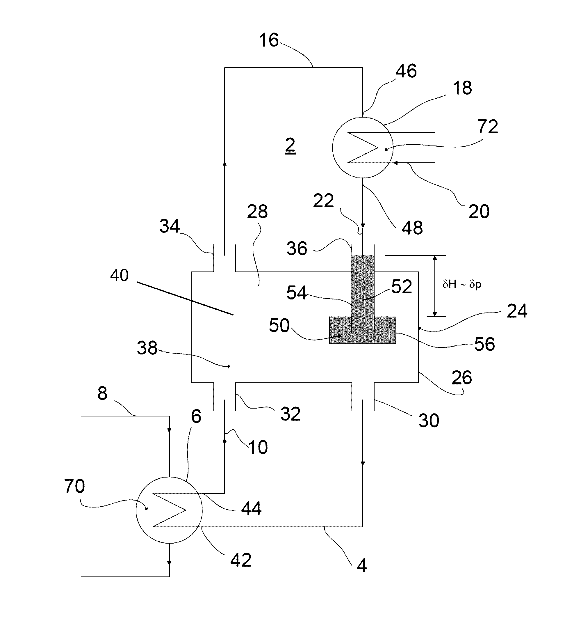
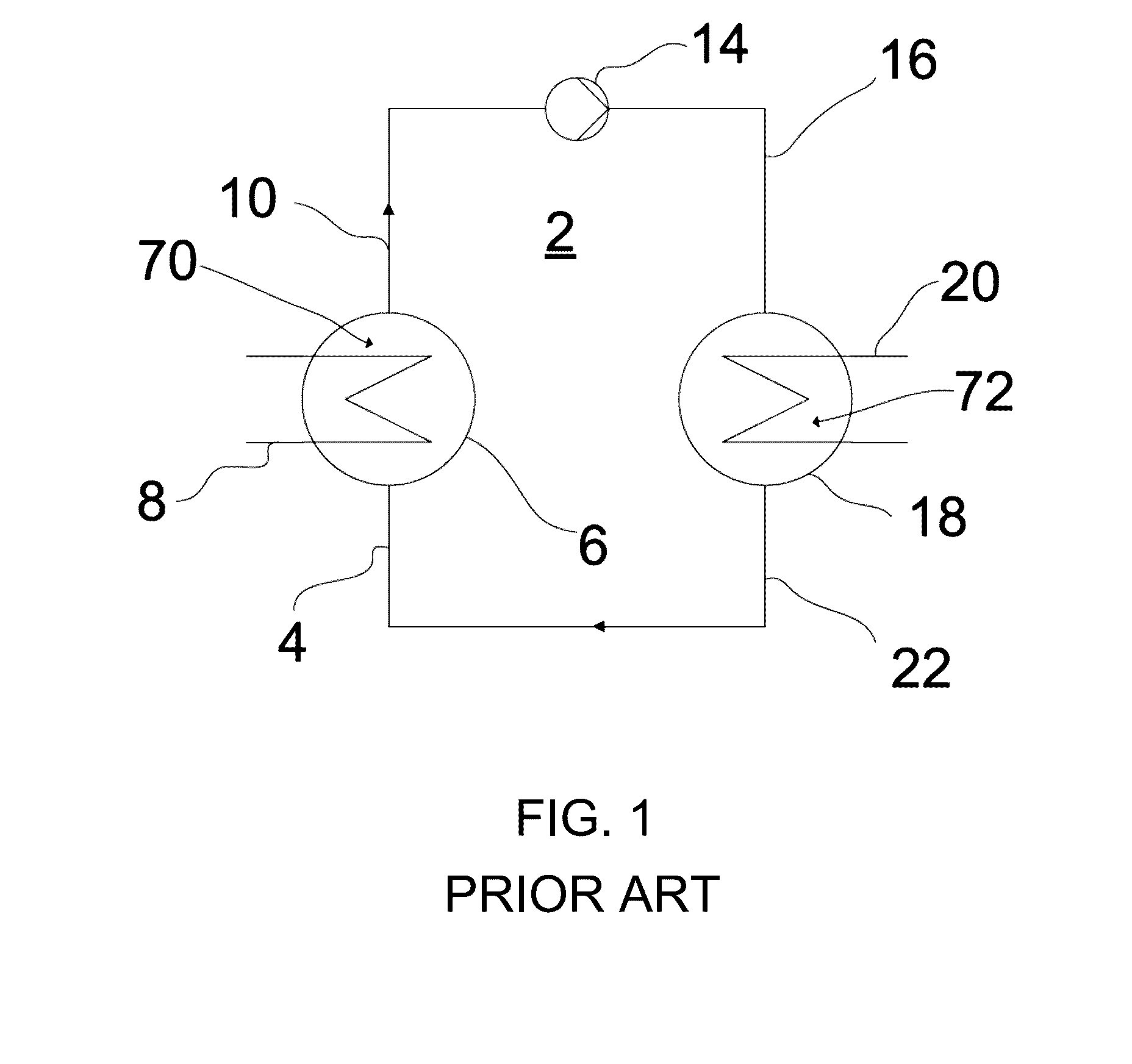
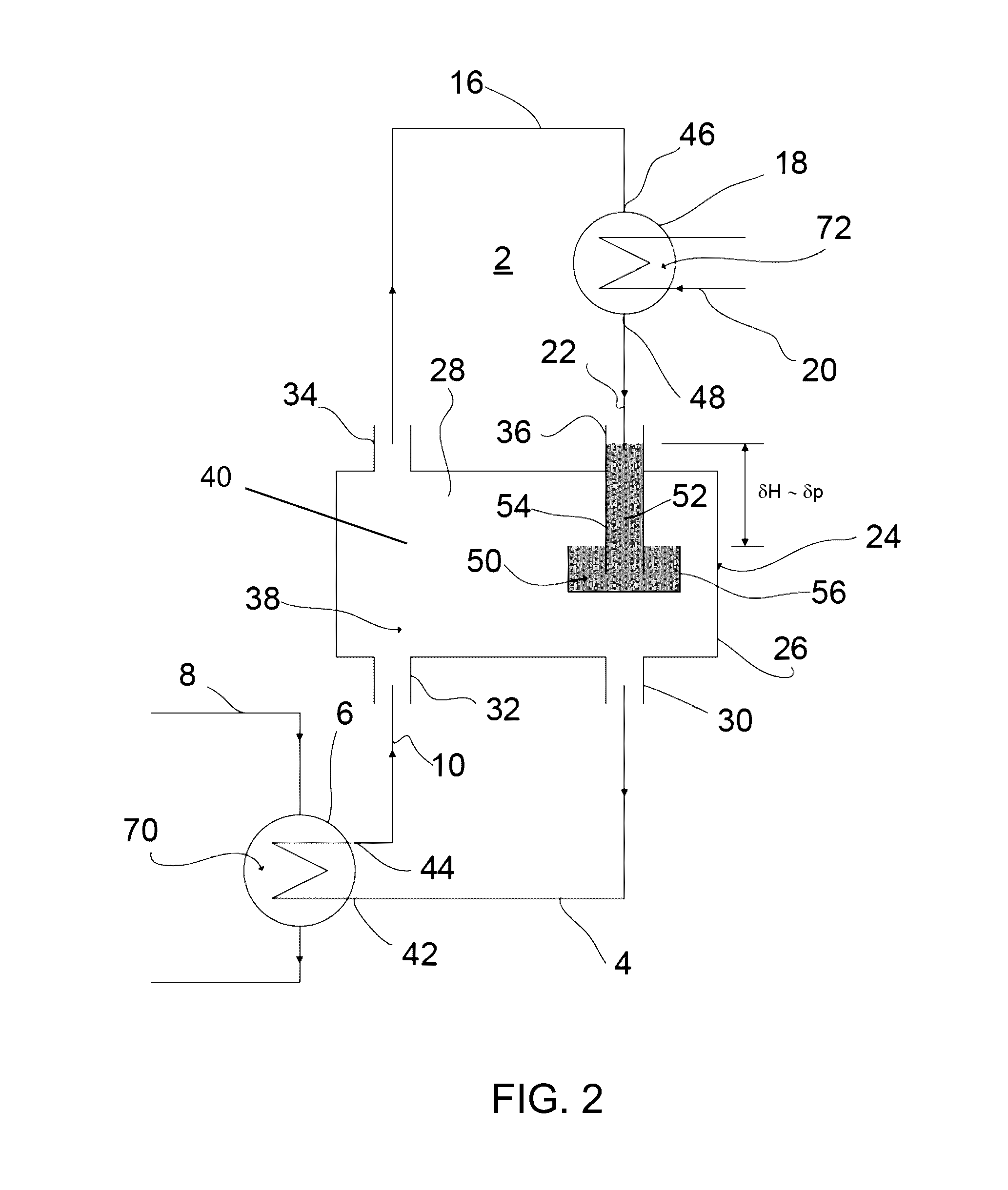
[0023]Referring now in detail to the figures of the drawings which show an embodiment of the invention in a very simplified and schematic form in which like parts or parts having like effects are provided with the same reference numerals and first, particularly, to FIG. 1 thereof, there is seen a schematic overview of a conventional cooling circuit 2, as is used in various technical applications which relate to transporting away excess heat from heated regions of facilities. The directions of flow of the fluids in question are illustrated in each case by flow arrows.

[0024]A coolant conducted in a circuit firstly enters a vaporizer 6 in liquid form through a vaporizer supply line 4 (also referred to as a vaporizer intake or feed line). The vaporizer 6 is in the form of a heat exchanger which is heated by using a thermally coupled heat source 70, which is shown herein purely by way of example in the form of a heating pipe 8 conducting a heating medium. The coolant is vaporized at leas...


PUM


Abstract

A passive two-phase cooling circuit includes a vaporizer and a condenser for a coolant conducted in the cooling circuit. A vaporizer supply line and a vaporizer discharge line are connected to the vaporizer, and a condenser supply line and a condenser discharge line are connected to the condenser. The cooling circuit has a simple and cost-effective structure which reduces or even completely prevents pressure shocks during operation by connecting the vaporizer supply line, the vaporizer discharge line, the condenser supply line and the condenser discharge line to a common damping container. A liquid column forms in the condenser discharge line during the operation of the cooling circuit and the column assumes the function of a liquid-tight seal and of a fluid-dynamic vibration damper.

Description

CROSS-REFERENCE TO RELATED APPLICATION[0001]This is a continuation application, under 35 U.S.C. §120, of copending International Application PCT / EP2015 / 055529, filed Mar. 17, 2015, which designated the United States; this application also claims the priority, under 35 U.S.C. §119, of German Patent Application DE 10 2014 205 086.3, filed Mar. 19, 2014; the prior applications are herewith incorporated by reference in their entirety.BACKGROUND OF THE INVENTIONField of the Invention[0002]The invention relates to a passive two-phase cooling circuit including a vaporizer and a condenser for a coolant conducted in the cooling circuit, a vaporizer supply line and a vaporizer discharge line connected to the vaporizer, a condenser supply line and a condenser discharge line connected to the condenser, the vaporizer supply line, the vaporizer discharge line, the condenser supply line, and the condenser discharge line being connected to a common damping container. A liquid column of liquid coola...

Claims


Application Information

Patent Timeline
IPC IPC(8): F28D15/02F28F19/00
CPCF28D15/0266F28D15/025F28F19/00F28F2265/30F28F2265/12F28F2230/00F28D2015/0216H05K7/20309H05K7/20318H05K7/20327F25B2339/04F25B2339/02F25B23/006F25B41/40F25B39/02F25B2500/13
Inventor FUCHS, THOMASORNOT, LEORECK, MARKUSREUTER, MATTHIAS
Owner FRAMATOME GMBH
Learn More