
Laser welding method and laser welding device

a laser welding and laser beam technology, applied in the field of laser welding, can solve the problems of limited heat transfer area and laser beam irradiation area, and achieve the effect of reducing pores and controlling pores

Active Publication Date: 2017-01-05
PANASONIC INTELLECTUAL PROPERTY MANAGEMENT CO LTD
View PDF5 Cites 11 Cited by
  • Summary
  • Abstract
  • Description
  • Claims
  • Application Information

AI Technical Summary

Benefits of technology

This patent describes a way to use laser welding to reduce the formation of pores in a weld. By first using laser energy to discharge zinc vapor, and then using another laser to perform the main welding, the method ensures that the pores and other negative effects of the zinc vapor are minimized. This technique allows for better control over the formation of pores and other defects in the weld.

Problems solved by technology

Because of a reduced energy of the laser beam for the first laser irradiation, an area irradiated with the laser beam and an area from which zinc is evaporated due to heat transfer may be limited.
Therefore, the first laser irradiation may fail to sufficiently discharge a zinc vapor, and the second laser irradiation may further generate a zinc vapor due to heat transfer, in which case porosities might be created.

Method used


Image

  • Laser welding method and laser welding device
  • Laser welding method and laser welding device
  • Laser welding method and laser welding device

Examples


first exemplary embodiment

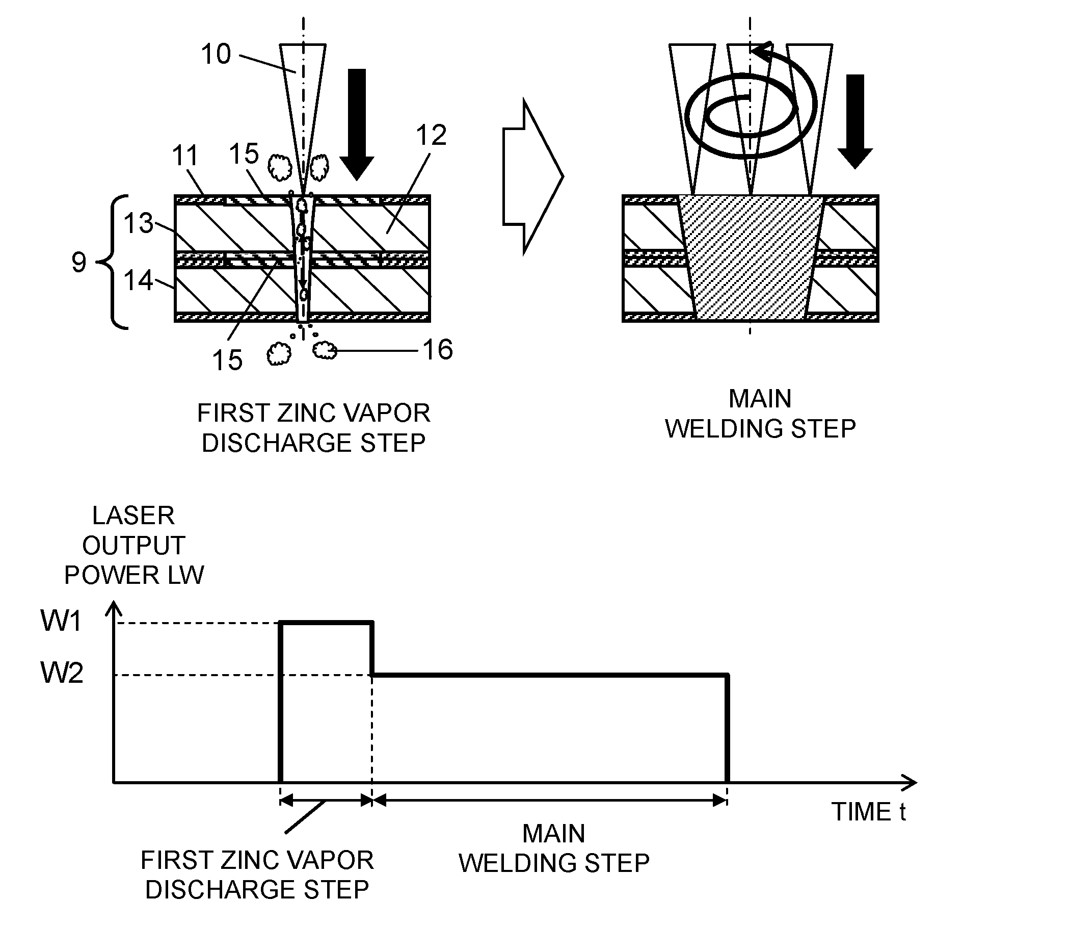
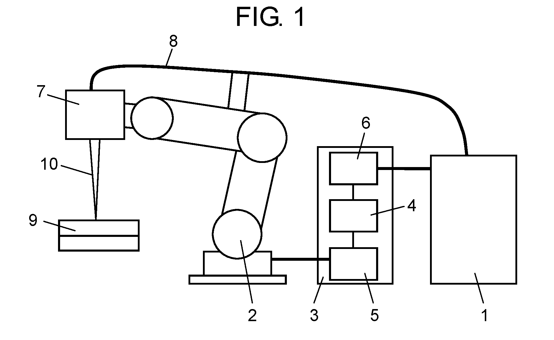
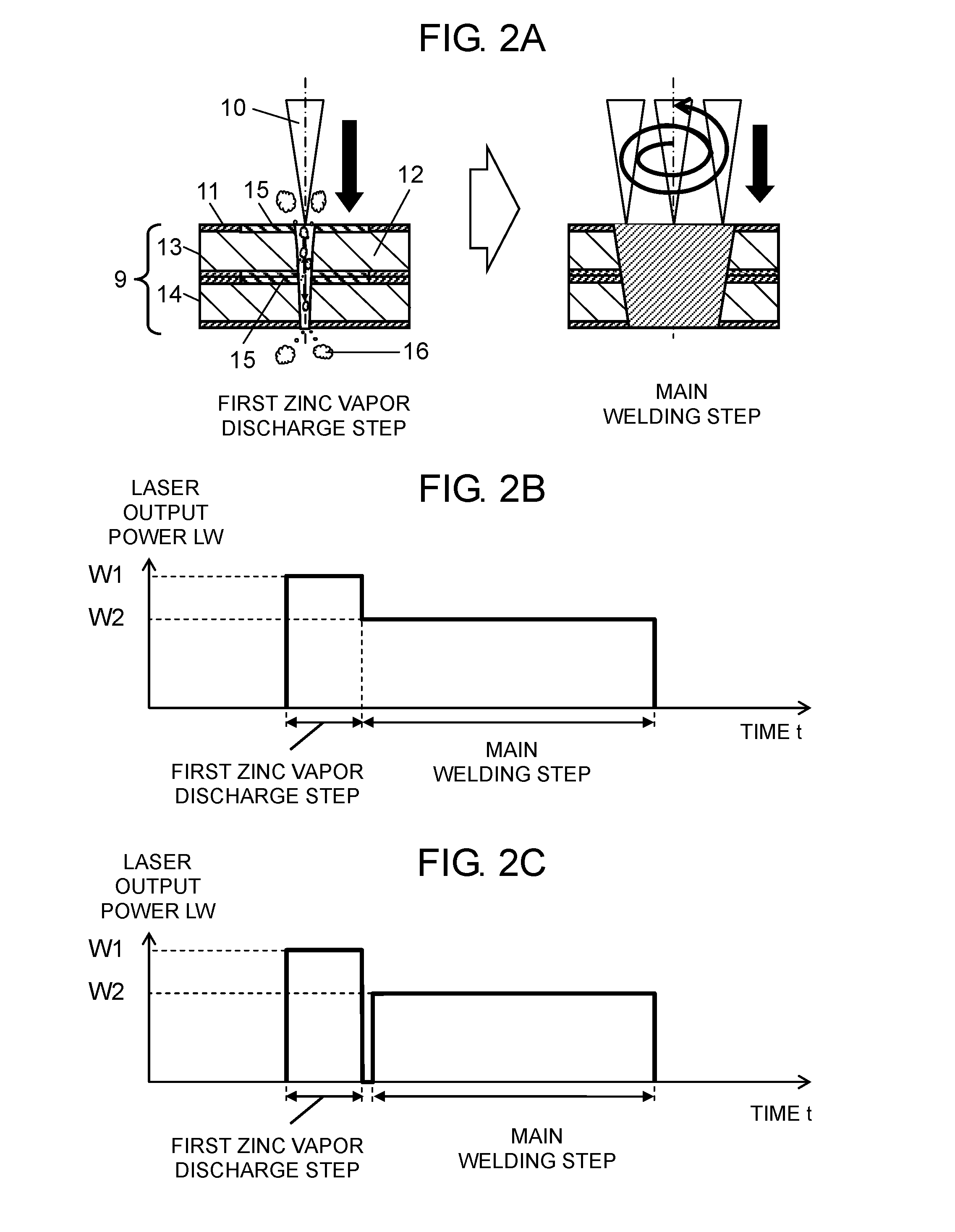
[0031]A first exemplary embodiment will be described with reference to FIG. 1 to FIG. 2C. FIG. 1 illustrates a schematic configuration of a laser welding device in this exemplary embodiment. FIG. 2A illustrates steps of a laser welding method in this exemplary embodiment. FIG. 2B is a graph indicating laser output power in the laser welding method in this exemplary embodiment. FIG. 2C is a graph indicating laser output power in another laser welding method in this exemplary embodiment. In FIG. 2B and FIG. 2C, the horizontal axis represents a time t and the vertical axis represents laser output power LW.

[0032]As illustrated in FIG. 1, a laser welding device in this exemplary embodiment includes laser oscillator 1, robot 2, controller 3 (control unit), laser irradiation head 7 (laser head), and optical fiber 8.

[0033]Laser oscillator 1 is connected to controller 3 and to a first end of optical fiber 8. Laser oscillator 1 outputs a laser beam, and then the laser beam enters optical fibe...

second exemplary embodiment

[0046]A second exemplary embodiment will be described with reference to FIG. 3A to FIG. 5. FIG. 3A illustrates steps of a laser welding method in this exemplary embodiment. FIG. 3B is a graph indicating laser output power in the laser welding method in this exemplary embodiment. FIG. 3C is a graph indicating laser output power in another laser welding method in this exemplary embodiment. FIG. 4 illustrates an effect produced by a relationship between laser output power and a laser irradiation time in a first zinc vapor discharge step. FIG. 5 illustrates an effect produced by a relationship between laser output power and a number of revolutions of a spiral movement in a second zinc vapor discharge step.

[0047]A laser welding device in this exemplary embodiment will not be described, because this laser welding device is identical to the laser welding device in the first exemplary embodiment.

[0048]A laser welding method in this exemplary embodiment will be described with reference to FI...


PUM

PropertyMeasurementUnit
boiling pointaaaaaaaaaa
melting pointaaaaaaaaaa
circumferenceaaaaaaaaaa

Abstract

A laser welding method of the present disclosure includes a first step, a second step, and a third step. In the first step, a first workpiece and a second workpiece are stacked on each other. Each of the first workpiece and the second workpiece has a surface coated with a first material and is made of a second material, which is different from the first material. In the second step, a first region in which the first workpiece and the second workpiece are stacked on each other is irradiated with a laser beam so that the laser beam penetrates both the first workpiece and the second workpiece. In the third step, a second region including the first region is irradiated with a laser beam in a spiral fashion.

Description

TECHNICAL FIELD[0001]The present disclosure relates to a laser welding method and a laser welding device that stack surface-treated members such as galvanized steel plates or the like on each other and then weld the stacked members by using a laser. More specifically, the present disclosure relates to laser welding that is effective in reducing formation of blowholes and pits.BACKGROUND ART[0002]Galvanized steel plates have superior resistance to rust and corrosion. For that reason, recently, galvanized steel plates have been used for automotive parts, architectural steel frames, and other members. Such galvanized steel plates are welded in accordance with their applications.[0003]A conventional laser welding method described in PTL 1 will be described with reference to FIG. 6A to FIG. 7B. FIG. 6A and FIG. 7A are perspective views to explain a conventional laser welding method. FIG. 6B is a cross section view related to FIG. 6A, which explains the conventional laser welding method; ...

Claims


Application Information

Patent Timeline
Patent Type & Authority Applications(United States)
IPC IPC(8): B23K26/322B23K26/00B25J11/00B23K26/244
CPCB23K26/322B23K26/244B23K26/0006G05B2219/45135B23K2201/34B23K2203/04B23K2201/006B25J11/005B23K26/22B23K26/082B23K2103/08B23K2101/006B23K2101/34B23K2103/04
Inventor FUJIWARA, JUNJIMUKAI, YASUSHIKAWAMOTO, ATSUHIRONAKAGAWA, TATSUYUKIMATSUOKA, NORIYUKI
Owner PANASONIC INTELLECTUAL PROPERTY MANAGEMENT CO LTD
Features
  • Generate Ideas
  • Intellectual Property
  • Life Sciences
  • Materials
  • Tech Scout
  • Unparalleled Data Quality
  • Higher Quality Content
  • 60% Fewer Hallucinations
Learn More