Method for producing plugged honeycomb structure

Active Publication Date: 2017-01-05
NGK INSULATORS LTD
View PDF0 Cites 0 Cited by
  • Summary
  • Abstract
  • Description
  • Claims
  • Application Information

AI Technical Summary

Benefits of technology

The present invention relates to a method for producing a plugged honeycomb structure. The method prevents plugging slurry from adhering to the inner surface of adjacent cells and the honeycomb structure's circumferential wall, which results in easier cleaning and reduced production costs. In summary, the technical effect of the patent is to simplify the production process and reduce manufacturing costs.

Problems solved by technology

Consequently, in a case where when performing the method described in Patent Document 1, even an image in which an area ratio to the predetermined cell area is comparatively small is regarded as the cell in the image after the binarization processing to prevent generation of the outermost circumferential cell in which the plugging portion is not formed, the problem occurs as follows.
Further, in such a case, the plugging slurry passing though the holes formed in the sheet leaks to the other adjacent cells or the outside of the honeycomb structure to adhere to inner peripheral surfaces of the other cells or a circumferential wall of the honeycomb structure.
As a result, after forming the plugging portions, there is required a step of removing the plugging slurry adhered to the inner peripheral surfaces of the other adjacent cells or the circumferential wall of the honeycomb structure as described above, which causes increase of the number of producing steps and accompanying rise of producing cost.
Further, in this case, the perforation processing is performed even at the position on the sheet on the outer side from the circumference of the end face of the honeycomb structure, and the plugging slurry passing through the holes formed by this perforation processing leaks out from the honeycomb structure, thereby adhering to a circumferential wall of the honeycomb structure.
As a result, after forming the plugging portions, there is required a step of removing the plugging slurry adhered to the circumferential wall of the honeycomb structure as described above, which causes the increase of the number of the producing steps and the accompanying rise of the producing cost.

Method used


Image

  • Method for producing plugged honeycomb structure
  • Method for producing plugged honeycomb structure
  • Method for producing plugged honeycomb structure

Examples


example 1

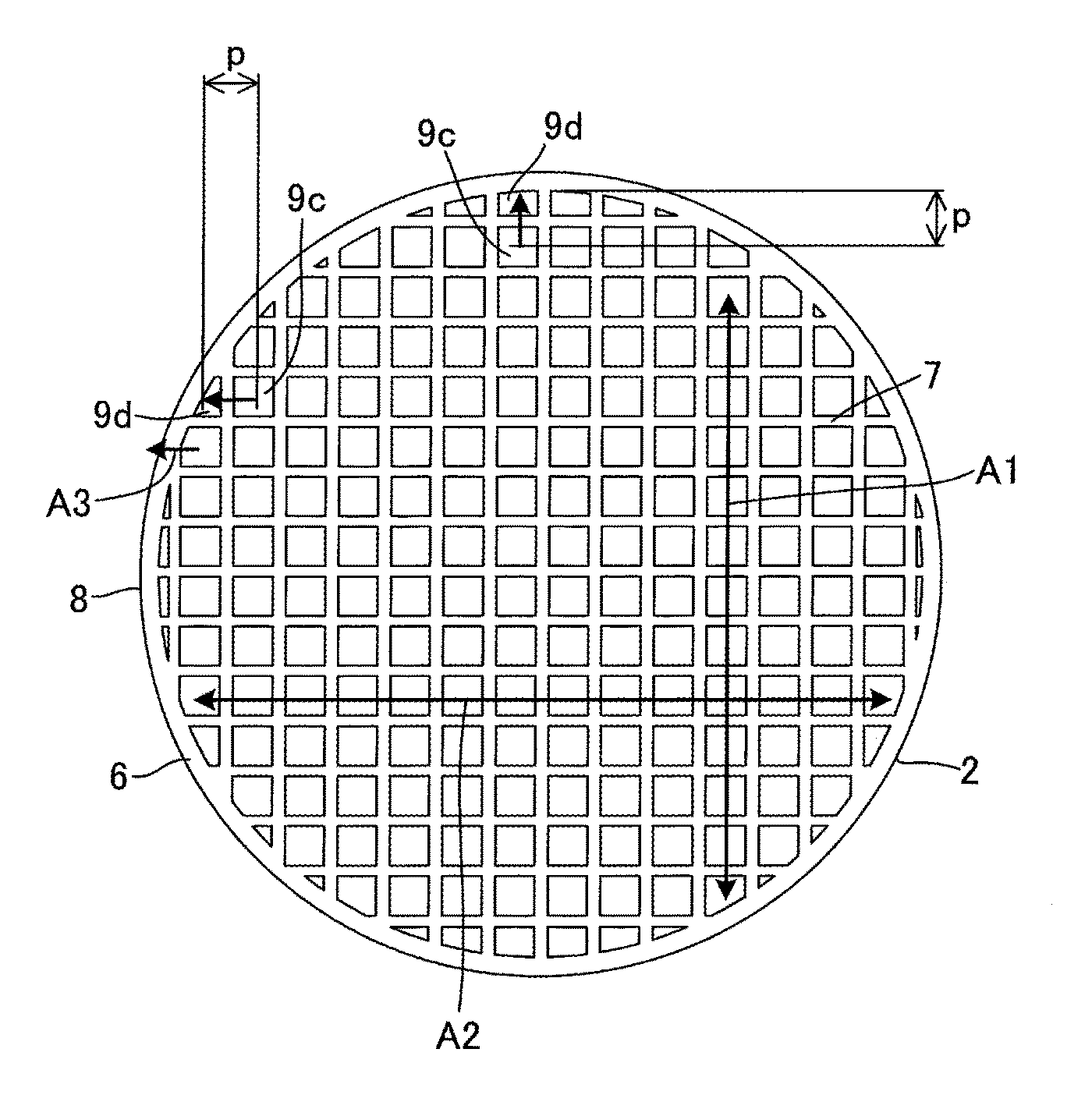
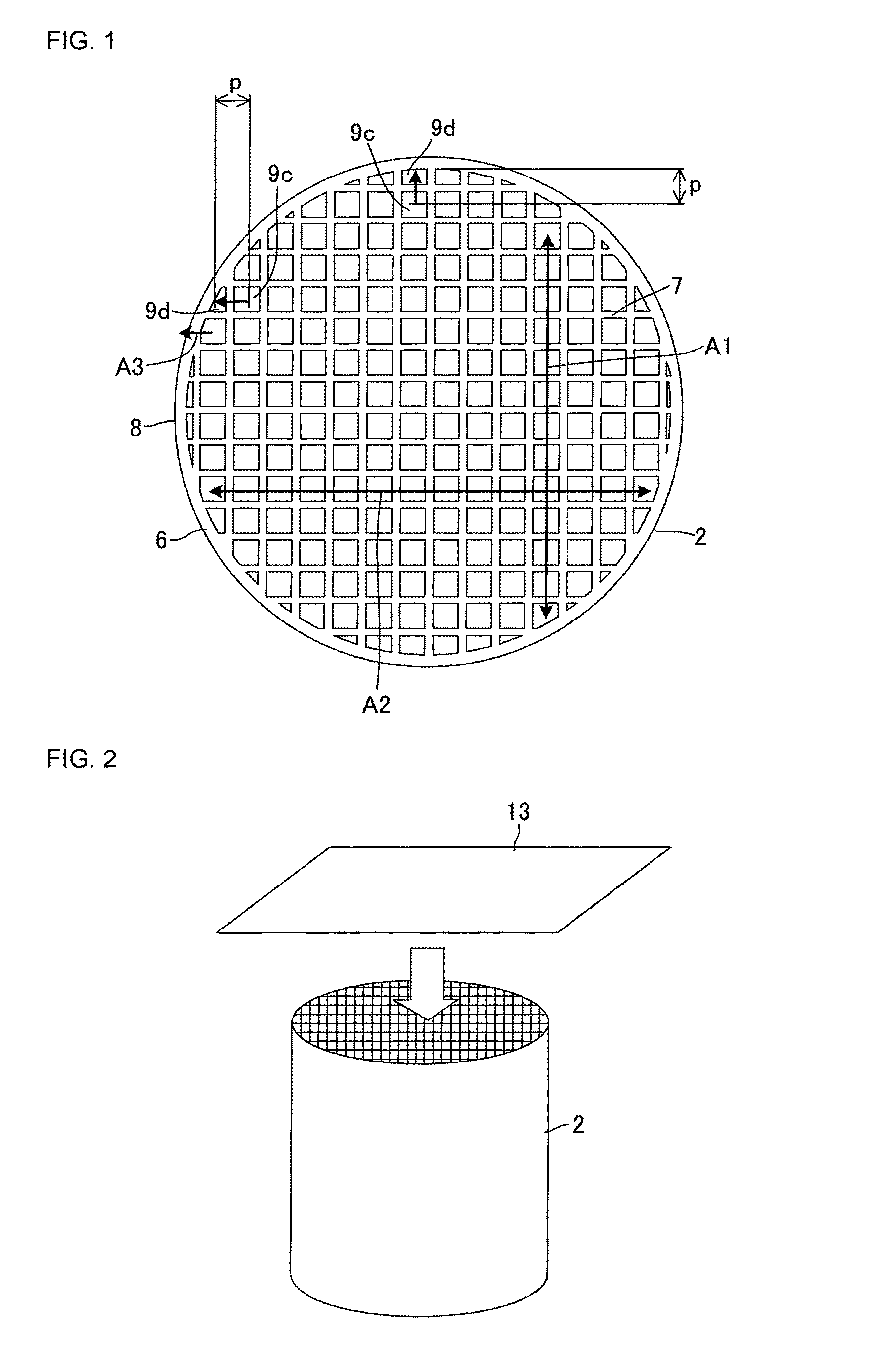
[0064]A commercially available transparent adhesive sheet was attached to an end face of a porous honeycomb structure made of cordierite. In the honeycomb structure, there was used a honeycomb structure in which a length was 150 mm, an outer diameter was 140 mm, a partition wall thickness was 300 μm, a cell shape (a shape of a usual cell) was square, a cell density was 300 cpsi (46.5 cells / cm2), and a designed cell pitch was 1.5 mm. The end face of the honeycomb structure to which the adhesive sheet was attached was imaged with a CCD camera, to subject an obtained image to image processing (binarization processing), and in a case where a black image of one block in the processed image reached 80% or more of a cell area of predetermined design, the image was regarded as the usual cell, to recognize a position of the cell. Additionally, an image resolution of the image processing was set to 0.06 mm / pixel. Furthermore, an average cell pitch was calculated from the usual cells whose pos...

example 2

[0065]The procedure of Example 1 was repeated to perform recognition of positions of usual cells and outermost circumferential cells, perforation processing to a sheet and formation of plugging portions, except that a honeycomb structure of a different structure was used. Afterward, it was checked whether or not a plugging slurry adhered to an inner peripheral surface of another cell adjacent to the outermost circumferential cell to be plugged and a circumferential wall of the honeycomb structure, and Table 1 shows the result. Additionally, in the honeycomb structure, there was used a honeycomb structure in which a length was 300 mm, an outer diameter was 300 mm, a partition wall thickness was 300 μm, a cell shape (a shape of the usual cell) was square, a cell density was 200 cpsi (31 cells / cm2), and a designed cell pitch was 1.8 mm.

example 3

[0066]The procedure of Example 1 was repeated to perform recognition of positions of usual cells and outermost circumferential cells, perforation processing to a sheet and formation of plugging portions, except that a honeycomb structure of a different structure was used. Afterward, it was checked whether or not a plugging slurry adhered to an inner peripheral surface of another cell adjacent to the outermost circumferential cell to be plugged and a circumferential wall of the honeycomb structure, and Table 1 shows the result. Additionally, in the honeycomb structure, there was used a honeycomb structure in which a length was 230 mm, an outer diameter was 230 mm, a partition wall thickness was 300 μm, a cell shape (a shape of the usual cell) was square, a cell density was 100 cpsi (15.5 cells / cm2), and a designed cell pitch was 2.5 mm.


PUM

PropertyMeasurementUnit
Circumferenceaaaaaaaaaa

Abstract

The present invention includes recognizing, as positions of outermost circumferential cells, positions each of which is calculated from an average cell pitch of usual cells and each of which is present on an inner side from a circumference of an end face of a honeycomb structure; disposing, on the basis of the recognition, virtual perforation regions at positions on a sheet which correspond to the outermost circumferential cells to be plugged, each of the virtual perforation regions being divided into a plurality of squares; and performing perforation processing of perforating at least one of a plurality of squares in each of the virtual perforation regions. Positions and a number of squares to be perforated in each of the virtual perforation regions are individually set in accordance with each of the positions of the outermost circumferential cells to be plugged to which each of the virtual perforation regions corresponds.

Description

TECHNICAL FIELD[0001]The present invention relates to a method for producing a honeycomb structure (a plugged honeycomb structure) in which one end portion of each cell is plugged for use in a diesel particulate filter (DPF) or the like.BACKGROUND ART[0002]An exhaust gas emitted from an internal combustion engine such as a diesel engine includes a large amount of particulate matter (PM) in which carbon that becomes a cause for environmental pollution is a main component. Therefore, it is general that a filter (DPF) to trap (filter) the PM is mounted in each of exhaust systems of such engines.[0003]Usually, in the filter for use in such a purpose, there is used a plugged honeycomb structure 1 including a honeycomb structure 2 and plugging portions 11 as shown in FIG. 13 and FIG. 14. The honeycomb structure 2 has a structure in which a porous partition wall 7 defines and forms a plurality of cells 9 communicating between two end faces 3 and 5. The plugging portions 11 are arranged to ...

Claims


Application Information

Patent Timeline
IPC IPC(8): B28B11/00C04B38/00F01N3/022B32B38/00B01D46/24C04B35/195B32B37/14
CPCB28B11/007C04B35/195C04B38/0006B32B37/146B32B38/0004B01D2279/30B01D46/247F01N3/0222C04B2235/3481B32B2307/412B32B2310/0843B01D46/2474B01D46/2418F01N2330/06F01N2330/48Y02T10/12C04B38/0074B01D46/249
Inventor TANAKA, KENSUKEFUJIOKA, YASUMASA
Owner NGK INSULATORS LTD
Why Eureka
Try Eureka