Brushless DC motor

Inactive Publication Date: 2006-06-06
BLACK & DECKER INC
View PDF70 Cites 36 Cited by
  • Summary
  • Abstract
  • Description
  • Claims
  • Application Information

AI Technical Summary

Benefits of technology

[0006]Generally, existing brushless DC motors that provide a specified power output within a volume that is appropriate for portable power tools are too costly for the consumer market (by a factor of 10). The most significant factors driving the cost of a brushless DC motor are the power density, the cost of the permanent magnets and electronic components, and complex production procedures. Therefore, to reduce the cost of producing brushless DC motors either the cost of the permanent magnets must be reduced, the method of assembling the devices must be improved, or the power density must be increased. The cost of the permanent magnets can be reduced by using either smaller or less powerful permanent magnets. The power density of a brushless DC motor can be increased by using higher power PMs or reducing the resistance of the stator windings.
[0007]The present invention provides a system and method for reducing the cost of producing brushless DC motors. The brushless DC motor includes a rotor assembly that has an unmagnetized permanent magnet affixed to a shaft. The permanent magnet remains unmagnetized until the motor is partially assembled. A plurality of coils for producing a magnetic field are wound about t

Problems solved by technology

Brushed motors such as the PM brushed motors that are generally employed in power tools are susceptible to damaged brushes during rough handling.
Although brushless DC motors generally are more durable and provide higher speed and torque performance than similar size brushed motors, conventional brushless motors have daunting cost disadvantages.
Generally, existing brushless DC motors that provide a specified power output w

Method used


Image

  • Brushless DC motor
  • Brushless DC motor
  • Brushless DC motor

Examples


Embodiment Construction

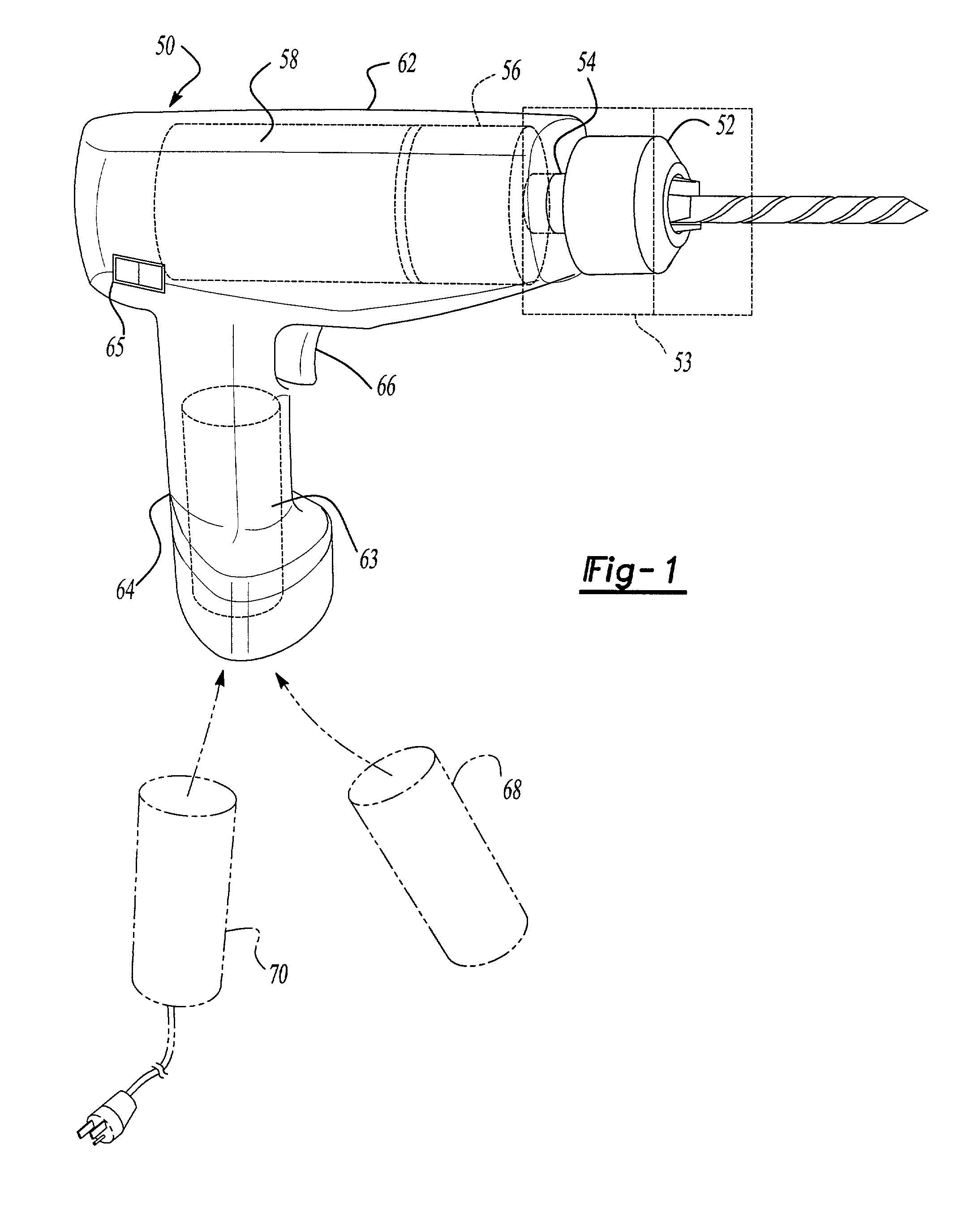
[0020]Referring to FIG. 1, a portable power tool 50 according to the present invention is shown. While the present invention is shown and described with a power drill 50, it will be appreciated that the particular tool is merely exemplary and could be a circular saw, a reciprocating saw, or any similar portable power tool constructed in accordance with the teachings of the present invention. The power tool 50 includes a tool interface 53 which is driven through a gear train 56 by a DC brushless motor 58. The tool interface in the preferred embodiment includes a chuck 52 secured to a rotatable spindle 54. The motor 58 is mounted within a housing 62 that includes a handle 64 extending therefrom. A trigger switch 66 is mounted in the handle 64 below the motor 58. A controller 65 coupled to the trigger switch supplies drive signals to the motor 58. The controller 65 is mounted below the motor 58 within the housing 62. Alternative locations for mounting the controller 65 include within t...


PUM


Abstract

A system and method for reducing the cost of producing a brushless DC motor (58) is presented. The brushless DC motor (58) provides higher power density and efficiency with an increased tool run time. The brushless DC motor (58) includes a rotor assembly (72) that has an unmagnetized permanent magnet (74) affixed to a shaft. The permanent magnet (74) remains unmagnetized until the motor is partially assembled. A plurality of coils (94) for producing a magnetic field are wound about the rotor assembly (72). The coils (94) include end turns that enclose the rotor assembly (72) such that the rotor assembly (72) is not removable. Since the windings (94) are wound with the rotor assembly (72) already enclosed, the windings (94) do not require large end coils to allow subsequent insertion of the rotor (72). Minimizing the end coils reduces the length of wire required per turn, thereby reducing the resistance of the winding (94). Also, since the permanent magnet (74) is unmagnetized when the coils (94) are wound around the rotor assembly (72) the winding process is simplified by not coupling energy into the wire which would influence the winder operation. The wound assembly is inserted into a stator stack (96) comprised of magnetic material that provides a magnetic flux return path for the magnetic flux generated by the permanent magnet (74). Using an unmagnetized permanent magnet (74) facilitates easy insertion of the wound assembly into the stator stack (96), reduces the accumulation of magnetic debris during the manufacturing process, and permits the motor assembly to be sealed prior to magnetizing the permanent magnet (74).

Description

CROSS-REFERENCE TO RELATED APPLICATIONS[0001]This application claims the benefit of the filing date of U.S. provisional application No. 60 / 175,133 filed on Jan. 7, 2000. U.S. Ser. No. 10 / 169,638 for “Brushless DC Motor” filed Oct. 17. 2002 is a National Staae of International application No. PCT / US01 / 00357 filed Jan. 5, 2001. This application claims the benefit of U.S. Provisional Application No. 60 / 175,133 filed Jan. 7, 2000. U.S. Ser. No. 09 / 742,839 for “Brushless DC Motor Sensor Control System and Method” (now U.S. Pat. No. 6,538,403) filed Dec. 20, 2000 also claims the benefit of U.S. Provisional Application No. 60 / 175,133.BACKGROUND AND SUMMARY OF THE INVENTION[0002]The present invention relates generally to electrically operated power tools and in particular, to power tools that are powered by a brushless DC motor.[0003]Over the past couple of decades the use of cordless power tools has increased dramatically. Cordless power tools provide the ease of a power assisted tool with...

Claims


Application Information

Patent Timeline
IPC IPC(8): H02P6/00H02K1/28H02K3/47H02K5/124H02K5/15H02K5/16H02K7/08H02K9/06H02K15/00H02K15/02H02K15/12H02K21/14H02K29/08H02P6/20
CPCH02K1/28H02K3/47H02K5/124H02K5/15H02K5/161H02K7/083H02K15/00H02K15/02H02K15/12H02K21/14H02K29/08H02P6/205Y10S388/937H02K9/06H02P6/21
Inventor WEAVER, J. MICHAELCLEANTHOUS, ARIS C.YAHNKER, CHRISTOPHER R.GORTI, BHANUPRASAD V.WALTER, RICHARD T.
Owner BLACK & DECKER INC
Why Eureka
Try Eureka