Cancer detector using deep optical scanning

a detection detector and deep optical scanning technology, applied in the direction of diagnostics using spectroscopy, instruments, applications, etc., can solve the problems of patient ionizing radiation, inability to detect malignant tumors in some patients, and uncomfortable patients

Active Publication Date: 2017-01-12
TELEBYTE
View PDF9 Cites 17 Cited by
  • Summary
  • Abstract
  • Description
  • Claims
  • Application Information

AI Technical Summary

Benefits of technology

[0023]Example embodiments include a detection system with opto-electronic elements and computational elements configured for portability. Such elements include, for example, avalanche photo diodes that efficiently convert reflected optical signals into electrical signals...

Problems solved by technology

However, mammography requires compression of the breast, which is often uncomfortable for the patient.
Mammography also exposes the patient to ionizing radiation and may fail to detect malignant tumors in some patients, especially younger individuals such as those less than 50 years old, and those with dense breast tissue.
Most guidelines do not recommend routine mammography for such patients because of concerns regarding the effects of radiation exposure and false positive identification rates.
Also, mammography, MRI, ultrasonography, and microwave imaging cannot be performed in a primary care physician's office or at Critical Care Clinics (CCCs).
However, DOS is typically only applicable when the suspected neoplastic tissue is within several centimeters of the surface of the body.
However, a certain quantity of light penetrates deeply into the breast and interacts with the underlying tissue in a nonlinear manner.
First, there is a need to make the device or system small enough to be portable so that it can be conveniently located and employed in a physician's office or a CCC, rather than at a centralized laboratory. The system should...

Method used


Image

  • Cancer detector using deep optical scanning
  • Cancer detector using deep optical scanning
  • Cancer detector using deep optical scanning

Examples


Embodiment Construction

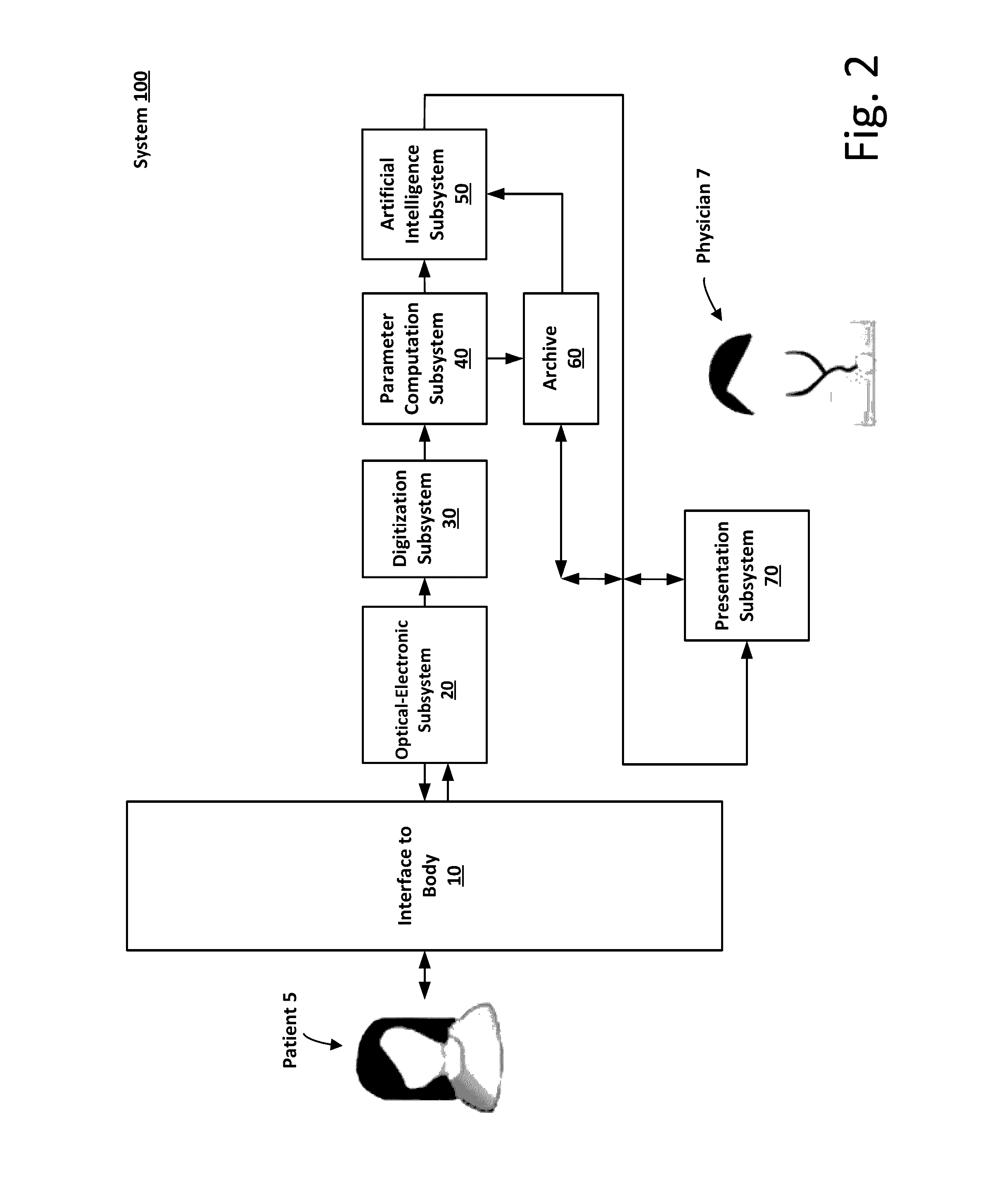
[0042]FIG. 2 is a block diagram of a system 100 for cancer detection according to an example embodiment of the present invention. The system 100 may be implemented as a single, portable device. Alternatively, the system 100 may be implemented as a plurality of separate components that may be in wired or wireless communication with each other. The system 100 may include an Interface 10 to the body of a patient 5, an Optical-Electronic Subsystem 20, a Digitization Subsystem 30, a Parameter Computation Subsystem 40, an Artificial Intelligence Subsystem 50, an Archive 60, and a Presentation Subsystem 70. Each of these subsystems will be described separately and may be operated by a physician 7. However, it will be understood that subsystems can be combined into a single hardware and / or software arrangement. Some components may be remotely located, for example, components that carry out processing over the Internet via Cloud computing.

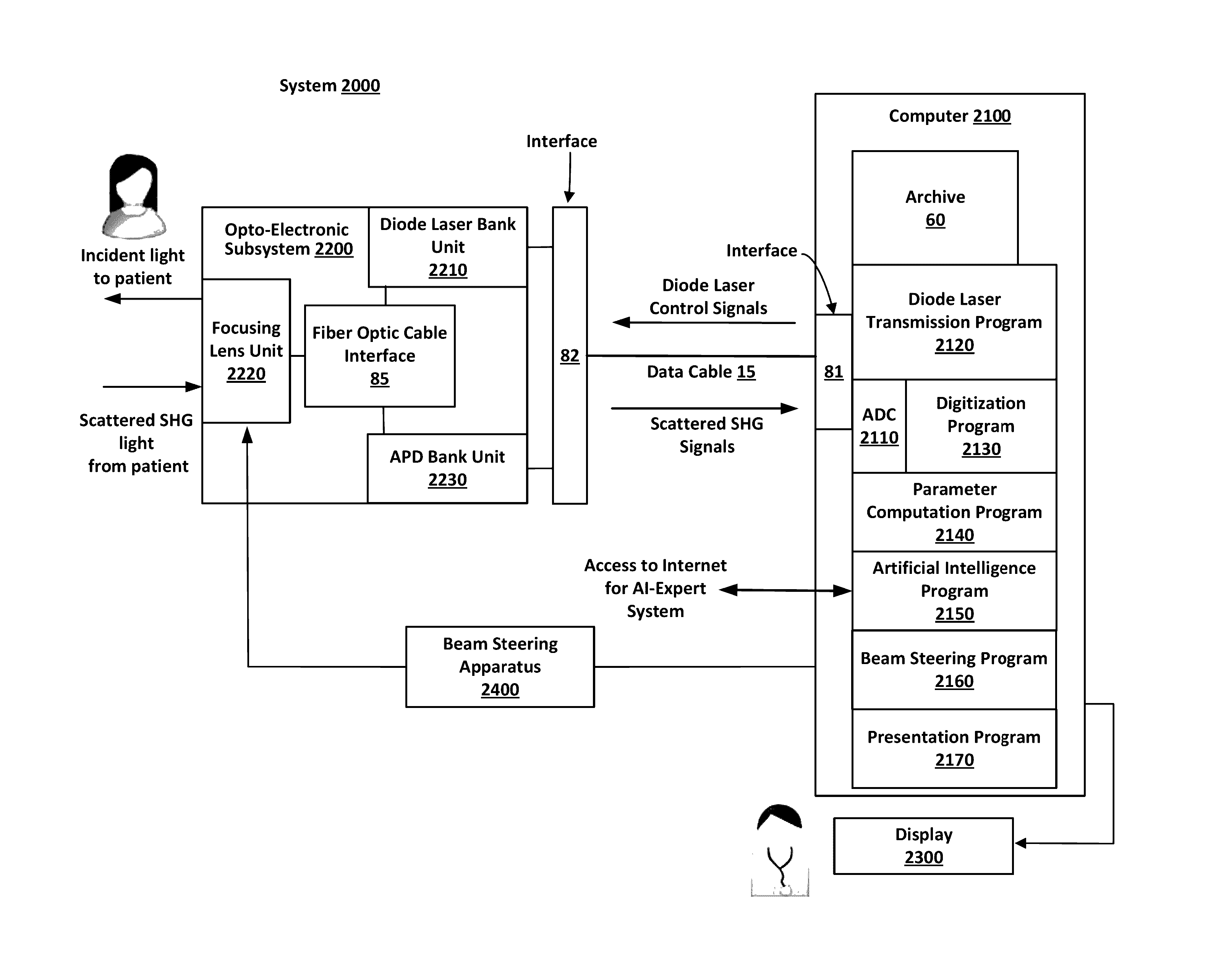
[0043]FIG. 3 is a block diagram showing the overall s...


PUM


Abstract

A device and a system, based upon Deep Optical Scanning (DEOS), for the detection of certain cancers such as breast cancer and the determination of their response to therapy. DEOS is based upon the nonlinear optical interaction of incident laser generated light with tissue. The cancers may either be subsurface or on the surface. The system includes hardware and software components that form subsystems including: an Optical Electronic Subsystem, a Digitization Subsystem, a Parameter Computation Subsystem, an Archive, an Artificial Intelligence Subsystem, and a Presentation Subsystem. The device can be made portable and is non-invasive in its application to a patient. The system can be integrated into a hybrid architecture with other imaging techniques used for the detection of cancers.

Description

CROSS-REFERENCE TO RELATED APPLICATIONS[0001]This application is a continuation-in-part of U.S. patent application Ser. No. 14 / 624,190, filed Feb. 17, 2015, which is herein incorporated by reference in its entirety.FIELD OF THE INVENTION[0002]The present invention relates to devices that use imaging techniques for the detection of certain subsurface and surface cancers, such as breast cancer, and the assessment of their response to therapy.BACKGROUND INFORMATION[0003]Cancer is a major cause of morbidity and mortality in the United States, and will be more so with the aging of the population. Early detection and classification of malignant tumors combined with accurate assessment of their response to therapy could have important implications, not only for patient care, but also from the public health and economic perspectives. Of particular interest is breast cancer, where malignant tumors may occur anywhere from on the surface to deep within the breast. In addition to surgical excis...

Claims


Application Information

Patent Timeline
IPC IPC(8): A61B5/00A61B10/02
CPCA61B5/7267A61B5/0035A61B5/0062A61B2576/00A61B5/7203A61B2562/0233A61B10/02A61B5/7228A61B5/743A61B8/0825A61B8/085A61B8/5223A61B5/0022A61B5/0075A61B5/0077A61B5/4842G16H40/67G16H30/40G16H50/30G16H40/63G16H50/20
Inventor BRENEISEN, MICHAELSCHNEIDER, KENNETH S.STROM, JOEL A.MURRAY, JOHN
Owner TELEBYTE
Why Eureka
Try Eureka