Transmitter optical signal to noise ratio improvement through receiver amplification in single laser coherent systems

a technology of optical signal and receiver, applied in the field of optical communication system, can solve the problem of limited output tx optical signal to noise ratio (osnr) and achieve the effect of improving the optical signal to noise ratio

Active Publication Date: 2017-01-12
NOKIA SOLUTIONS & NETWORKS OY
View PDF0 Cites 12 Cited by
  • Summary
  • Abstract
  • Description
  • Claims
  • Application Information

AI Technical Summary

Benefits of technology

[0006]According to one aspect, the invention features a transceiver having an improved optical signal to noise ratio, comprising: a transmitter having an electrical transmitter input port and an optical transmitter output port; a receiver having an optical receiver input port and an electrical receiver output port; a first coherent optical source shared between the transmitter and the receiver and configured to provide illumination with intensity PT to the transmitter and illumination with intensity PLO to the receiver; a second coherent optical source in optical communication with the optical transmitter output port by way of an optical coupler, the optical transmitter output port comprising a first optical amplifier, the second coherent optical source having a first optical feedback loop control; and a second optical amplifier configured to receive an input optical signal from the second coherent optical source, and to provide amplified illumination to an optical intensity controller, the optical intensity controller configured to provide controlled intensity illumination to the receiver, the optical intensity controller being part of a second feedback loop.

Problems solved by technology

In such a system using a Tx optical amplifier, the output Tx optical signal to noise ratio (OSNR) is typically limited by amplified spontaneous emission (ASE) noise due to the optical amplifier.

Method used


Image

  • Transmitter optical signal to noise ratio improvement through receiver amplification in single laser coherent systems
  • Transmitter optical signal to noise ratio improvement through receiver amplification in single laser coherent systems
  • Transmitter optical signal to noise ratio improvement through receiver amplification in single laser coherent systems

Examples


example implementation

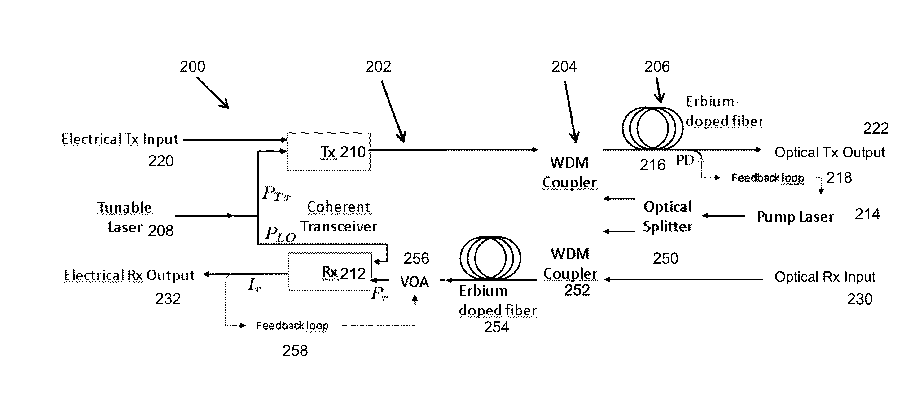
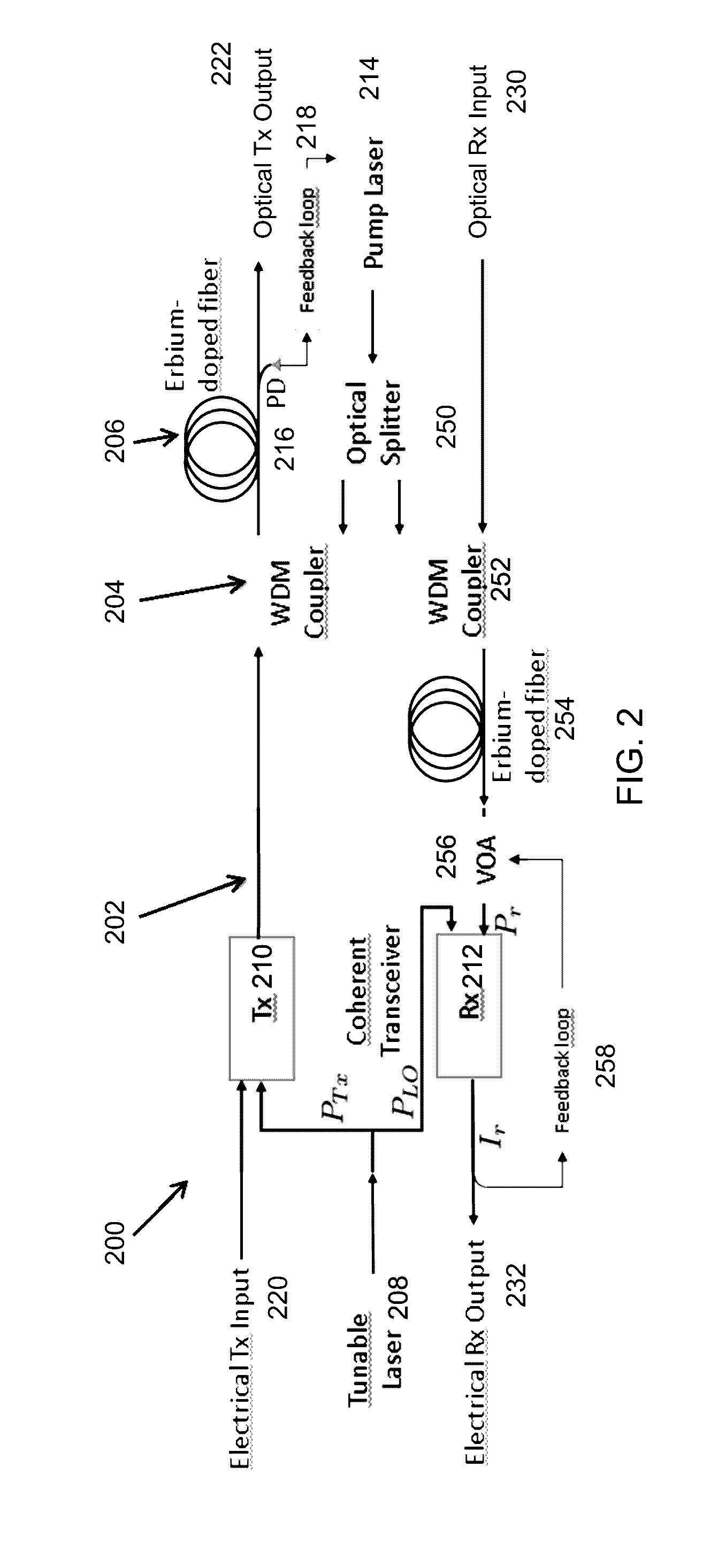
[0050]FIG. 2 is a schematic diagram of one embodiment of an apparatus having a single pump laser source for two amplification fiber coils (in the embodiment illustrated, the amplification fiber coils are Erbium-doped fiber amplifier coils) according to principles of the invention. The method of using a single pump laser source for two amplification fiber coils is also described. The required gain and output power in the Rx optical amplifier is much lower than in the Tx optical amplifier. Therefore, the optical splitter need only tap off a small fraction of the pump laser power for the Rx optical amplifier. In other embodiments, amplifiers other than EDFA amplifiers may be used.

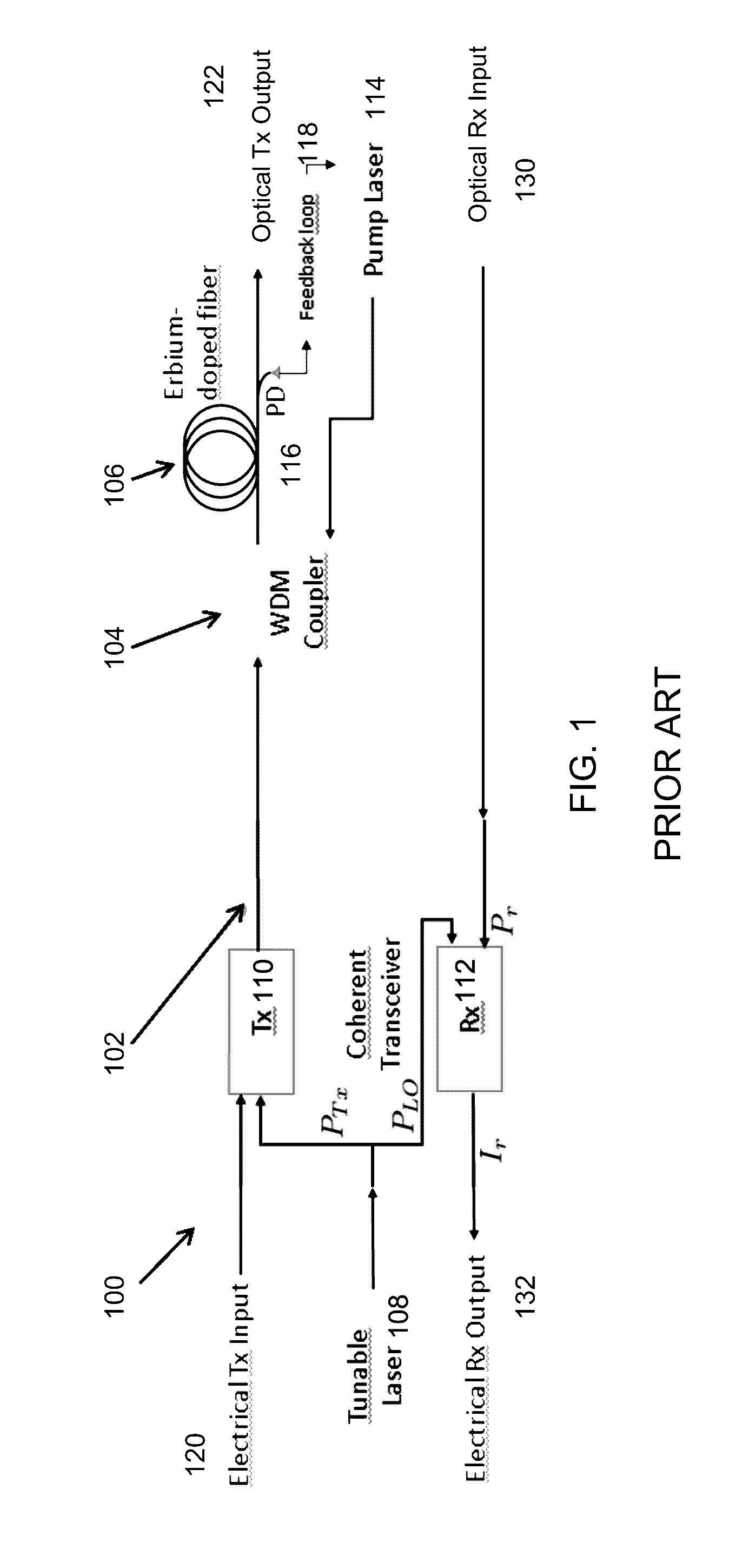
[0051]As illustrated in FIG. 2 is a schematic block diagram 200 of a prior art coherent optical transceiver 202, in which in-line power monitor photodiodes and fiber optic splices are omitted. The pump laser 214 provides illumination to an optical splitter 250 which can split the illumination in desired propor...


PUM


Abstract

A transceiver having an improved transmitter optical signal to noise ratio, and methods of making and using the same.

Description

FIELD OF THE INVENTION[0001]The invention relates to optical communication systems in general and particularly to a receiver for an optical communication system.BACKGROUND OF THE INVENTION[0002]In coherent optical communication systems, optical amplifiers are often used at the output of the transmitter (Tx). Additionally, in power- and cost-constrained systems, a single laser may be shared between the transmitter and local oscillator (LO) in the receiver (Rx). In such a system using a Tx optical amplifier, the output Tx optical signal to noise ratio (OSNR) is typically limited by amplified spontaneous emission (ASE) noise due to the optical amplifier. The OSNR can be improved by reducing the insertion loss of the transmitter or by increasing the laser power dedicated to the transmitter. Typically, both of these parameters are fixed.[0003]FIG. 1 is a schematic block diagram 100 of a prior art coherent optical transceiver 102, in which in-line power monitor photodiodes and fiber optic...

Claims


Application Information

Patent Timeline
Patent Type & Authority Applications(United States)
IPC IPC(8): H04B10/40
CPCH04B10/40H04B10/615H05K999/99
Inventor SAATHOFF, GUIDOSTRESHINSKY, MATTHEW AKIOPALMER, ROBERTWUTH, TORSTEN
Owner NOKIA SOLUTIONS & NETWORKS OY
Why Eureka
Try Eureka