Honeycomb filter

Active Publication Date: 2017-01-19
NGK INSULATORS LTD
View PDF0 Cites 3 Cited by
  • Summary
  • Abstract
  • Description
  • Claims
  • Application Information

AI Technical Summary

Benefits of technology

The present invention provides a honeycomb filter with improved regeneration efficiency and reduced pressure loss during deposition of particulate matters (PM). The filter has a predetermined state with inflow and outflow cells, and the conditions for the surface areas and pore diameter of the filter walls are met. This results in an increased effective geometric surface area (GSA) and lower pressure loss during PM deposition. The improved regeneration efficiency has been achieved by optimizing the surface area and pore diameter of the filter walls.

Problems solved by technology

Heretofore, in an internal combustion engine, generation of cinders during combustion of fuel has raised a problem.

Method used


Image

  • Honeycomb filter
  • Honeycomb filter
  • Honeycomb filter

Examples


example 1

[0096]As a ceramic raw material, a mixture of silicon carbide (SiC) powder and metal silicon (Si) powder at a mass ratio of 80:20 was prepared. To this mixed raw material, hydroxypropyl methylcellulose was added as a binder, a water absorbable resin was added as a pore former, and water was further added, to prepare a forming raw material. The obtained forming raw material was kneaded by using a kneader to obtain a kneaded material.

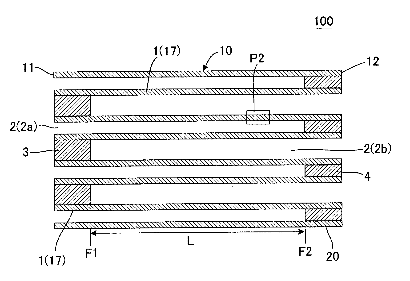
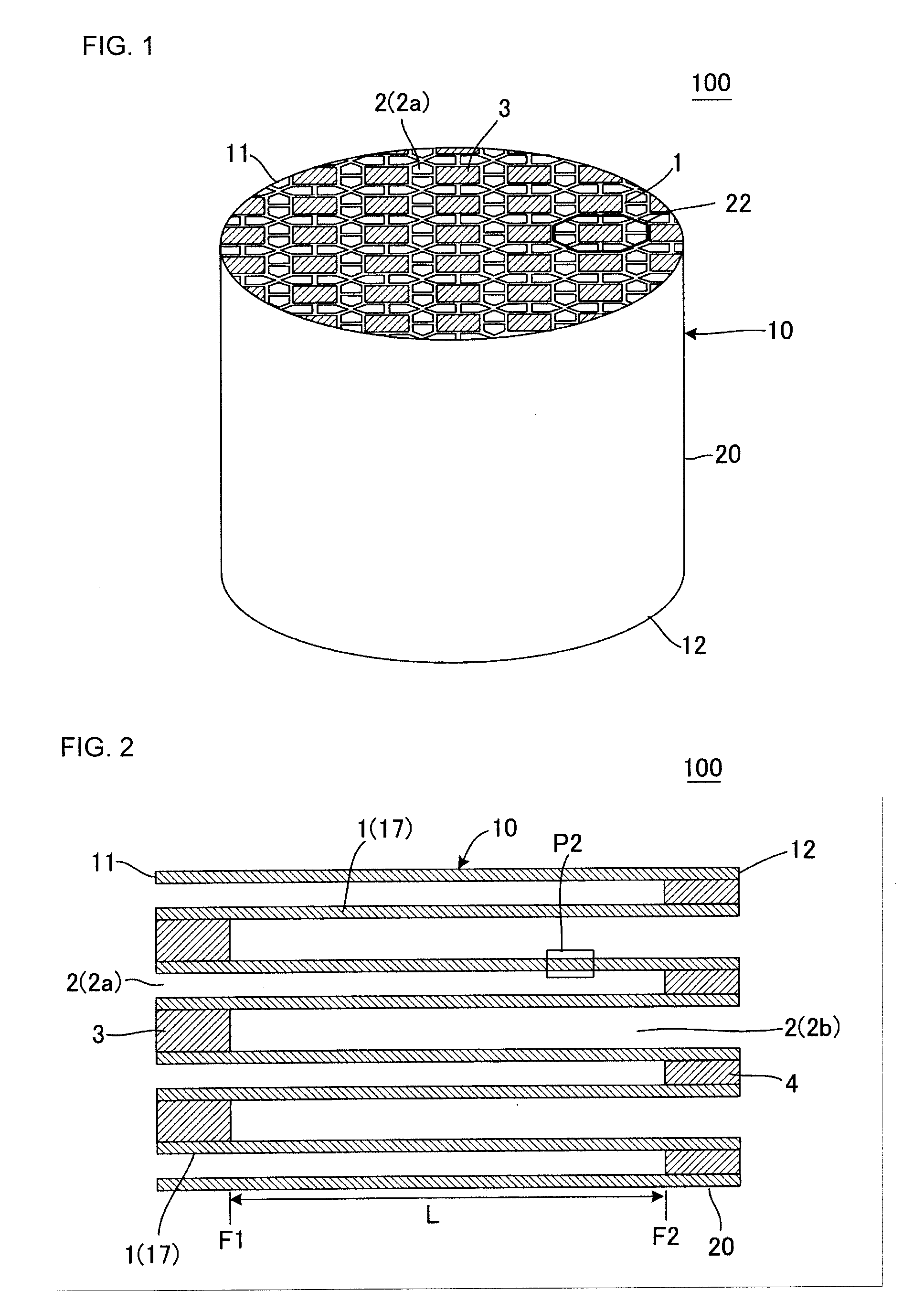
[0097]Next, the obtained kneaded material was formed by using a vacuum extruder, to prepare 16 quadrangular prismatic columnar honeycomb segments having a cell sectional structure shown in FIG. 1. In each of the obtained honeycomb segments, each end face had a vertical size of 35 mm×a horizontal size of 35 mm and a length in a cell extending direction was 152 mm.

[0098]Next, for the obtained honeycomb segments, high frequency induction heating and drying were performed, followed by drying with a hot air drier at 120° C. for 2 hours, to obtain honeycomb seg...


PUM

PropertyMeasurementUnit
Fractionaaaaaaaaaa
Fractionaaaaaaaaaa
Fractionaaaaaaaaaa

Abstract

A honeycomb filter includes a honeycomb structure body having porous partition walls defining a plurality of cells, inflow side plugging portions, and outflow side plugging portions, and in a cross section perpendicular to a cell extending direction, the whole periphery of each of outflow cells is surrounded by an inflow cell group, inflow cells are defined by inflow / outflow partition walls which are the partition walls defining the outflow cell and inflow / inflow partition walls which are the partition walls intersecting the inflow / outflow partition walls, a surface area A1 of the inflow / outflow partition wall of the inflow cell and a surface area A2 of the inflow / inflow partition wall of the inflow cell satisfy a relation of 1.2≦A1 / A2≦2, and in the partition wall, an average pore diameter of a surface region is from 4 to 60% of an average pore diameter of a central region.

Description

[0001]The present application is an application based on JP-2015-143418 filed on Jul. 17, 2015 with the Japan Patent Office, the entire contents of which are incorporated herein by reference.BACKGROUND OF THE INVENTION[0002]Field of the Invention[0003]The present invention relates to a honeycomb filter, and more particularly, it relates to a honeycomb filter which is excellent in regeneration efficiency and in which a pressure loss during deposition of a particulate matter is low.[0004]Description of the Related Art[0005]Heretofore, in an internal combustion engine, generation of cinders during combustion of fuel has raised a problem. To solve the problem, from a viewpoint of air pollution, it is considered that removal of harmful components included in an exhaust gas is required, and simultaneously, countermeasures are required to prevent a particulate matter (hereinafter abbreviated to “PM”) such as soot or ash from being discharged to the atmospheric air.[0006]In particular, ther...

Claims


Application Information

Patent Timeline
IPC IPC(8): B01D46/24F01N3/022
CPCB01D46/2429B01D46/244B01D2201/62B01D2046/2433B01D2046/2437F01N3/0222B01D46/2474B01D46/24492B01D46/24491B01D46/2484B01D46/2482B01D46/2486
Inventor MIYAIRI, YUKIO
Owner NGK INSULATORS LTD
Why Eureka
Try Eureka