Low-Frequency Band Suppression Enhanced Anti-Reversal Power System Stabilizer

US20170025978A1Active Publication Date: 2017-01-26ELECTRIC POWER RES INST OF STATE GRID ZHEJIANG ELECTRIC POWER COMAPNY +2

Image

  • Low-Frequency Band Suppression Enhanced Anti-Reversal Power System Stabilizer
  • Low-Frequency Band Suppression Enhanced Anti-Reversal Power System Stabilizer
  • Low-Frequency Band Suppression Enhanced Anti-Reversal Power System Stabilizer

Examples


Embodiment Construction

[0032]The invention is further illustrated in combination with all drawings of the instruction.

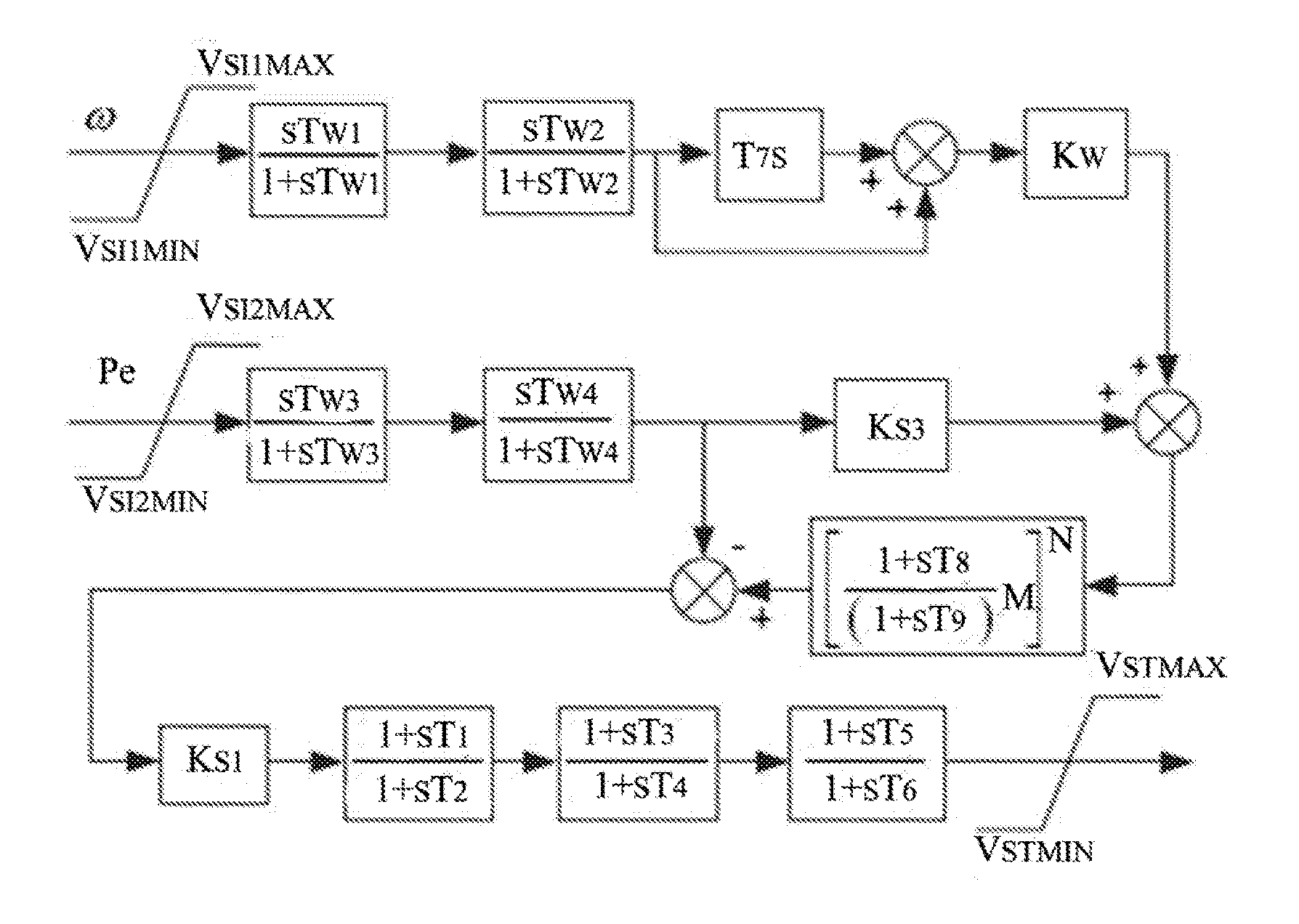
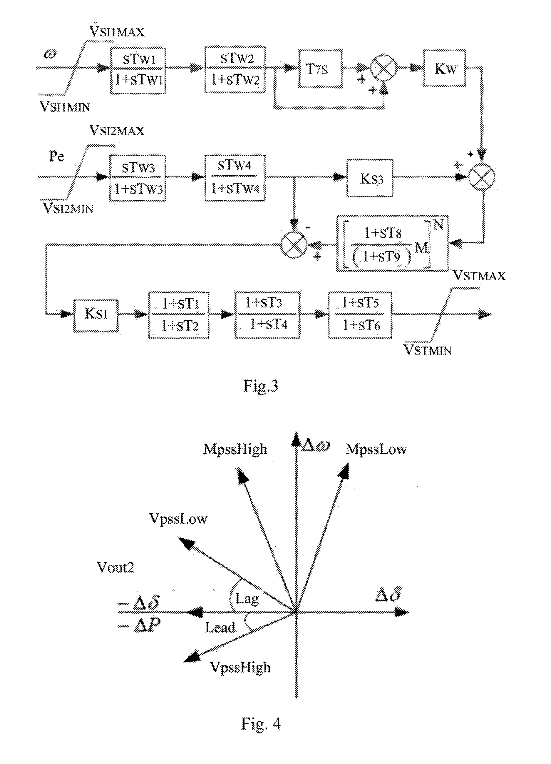
[0033]The structure of power system stabilizer (PSS-NEW-B) model is shown in FIG. 3. Its working steps are as follows:

[0034]Step 1: Check generator speed single ω. Use two-order DC blocking link to get speed fluctuation signal and then correct it by parallel proportional differential PD.

[0035]Step 2: Check active power signal of generator Pe, and use Order 2 DC blocking link to get fluctuation signal of active power.

[0036]Step 3: After gain by gain factor Ks3, the fluctuation signal of active power in Step 2 by is added with speed fluctuation signal corrected by PD in Step 1 together to become equivalent synthetic mechanical power.

[0037]Step 4: Use notching filter to conduct lowpass filtering for equivalent synthetic mechanical power received in Step 3.

[0038]Step 5: Subtract fluctuation signal of active power in Step 2 from signal in Step 4 (by lowpass filtering in notching filter) to get ...


PUM


Abstract

A low-frequency band suppression enhanced anti-reversal power system stabilizer is presented by the invention. Currently the widely used PSS2B power system stabilizer needs lead elements above Order 2 to meet the phase compensation requirement of DC blocking signal of active power, thus quickly increasing high-frequency band gain, restricting allowable total setting gain of PSS, limiting low-band gain and reducing low-frequency band suppression ability of power system stabilizer. The invention will add generator speed signal ω (which is treated by DC blocking element and corrected by parallel proportional differential PD) and active power signal Pe (which is treated by DC blocking element and gained by gain factor Ks3) to get equivalent synthetic mechanical power of power system stabilizer. The actual active power signal gained by gain factor KS1 can meet the requirement of phase compensation through Order 1 lead and lag elements, thus increasing allowable total setting gain of PSS and improving the ability of low-frequency band oscillation suppression.

Description

TECHNOLOGICAL FIELD[0001]The invention relates to power system stabilizer for low frequency oscillation suppression in the field of dynamic stability control of power system, which, to be specific, is a power system stabilizer with low-frequency band oscillation suppression capability and anti-reversal function.BACKGROUND OF THE INVENTION[0002]With rapid progress of robust intelligent power grid, a super-large AC synchronous power grid is gradually shaped up after grids networking in East China, North China and Central China. As backup and supporting system of high capacity DC ultra-high voltage power transmission system, the AC extra-high voltage greatly strengthens interconnection of power systems in different regions. The expansion of AC grid scale results in increase of equivalent inertia of overall power system, thus leading to increasingly low frequency oscillation of the system. In addition, it is inevitable for the remote heavy load AC transmission to cause reduction of syst...

Claims


Application Information

Patent Timeline
26 Jan 2017
Publication
US20170025978A1
IPC
H02P9/10
CPC
H02P9/105; H02P9/102
Inventors
WU, KUAYU; LU, CENCEN