Egr system for supercharging engine

a supercharging engine and egr technology, applied in the direction of machines/engines, mechanical equipment, electric control, etc., can solve the problems of engine performance reduction, and achieve the effect of preventing impeller erosion and extending the control range of the velocity of egr gas

Inactive Publication Date: 2017-02-02
TOYOTA JIDOSHA KK
View PDF32 Cites 15 Cited by
  • Summary
  • Abstract
  • Description
  • Claims
  • Application Information

AI Technical Summary

Benefits of technology

[0011]According to the present invention, the velocity of the EGR gas that flows out from the introduction port is changed in accordance with the flow rate of fresh air, whereby the EGR gas can be caused to flow toward the center portion of the impeller without extending the EGR pipe to the inside of the intake passage and guiding the EGR gas to the center of the intake passage. Therefore, prevention of erosion of the impeller by condensed water generated in the EGR passage, and restraint of the pressure loss of the intake air can be made compatible. In addition, according to the present invention, the EGR valve and the exhaust throttle valve are used in combination as means for changing the velocity of the EGR gas, and therefore, the control range of the velocity of the EGR gas can be enlarged. Thereby, the exit velocity necessary to flow toward the center portion of the impeller can be given to the EGR gas irrespective to the operation state of the engine.

Problems solved by technology

Therefore, there is the fear that the engine performance is reduced by increase in pressure loss of the intake air.

Method used


Image

  • Egr system for supercharging engine
  • Egr system for supercharging engine
  • Egr system for supercharging engine

Examples


first embodiment

[0023]Hereinafter, a first embodiment of the present invention will be described with reference to the drawings.

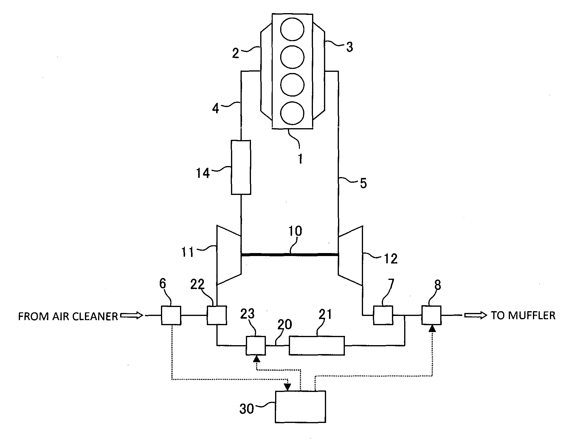
[0024]FIG. 1 is a diagram showing an entire configuration of a supercharging engine to which an EGR system according to the first embodiment of the present invention is applied. In the present embodiment, the type of supercharging engine is not limited. The supercharging engine may be a spark ignition type engine, or may be a compression ignition type engine. An engine main body 1 of the supercharging engine includes a plurality of cylinders. While FIG. 1 shows an example in which four cylinders are disposed in series, the number of cylinders and arrangement of the cylinders are not limited.

[0025]An intake manifold 2 is mounted to an intake side of the engine main body 1. Fresh air that is taken into an intake passage 4 from an air cleaner not illustrated is supplied to the respective cylinders of the engine main body 1 via the intake manifold 2. An airflow meter 6 that ou...

second embodiment

[0041]Next, a second embodiment of the present invention will be described with reference to the drawings.

[0042]FIG. 6 is a diagram showing an entire configuration of a supercharging engine to which an EGR system according to the second embodiment of the present invention is applied. In FIG. 6, the same reference signs are assigned to the components or parts common to the supercharging engine shown in FIG. 1. Further, explanation thereof will be omitted.

[0043]In the EGR system according to the present embodiment, the EGR passage 20 is directly connected to the intake passage 4. An EGR valve 25 is provided at a connecting portion of EGR passage 20 and the intake passage 4. The EGR valve 25 of the present embodiment is a poppet valve with a variable lift amount. The EGR valve 25 as well as the exhaust throttle valve 8 is controlled by the control device 30.

[0044]FIG. 7 is a sectional view showing a configuration of a vicinity of an introduction port 26 for an EGR gas of the EGR system...

third embodiment

[0054]Next, a third embodiment of the present invention will be described with reference to the drawings.

[0055]An EGR system according to the third embodiment of the present invention is also applied to the supercharging engine of the configuration shown in FIG. 6, similarly to the second embodiment. However, in the present embodiment, in place of the EGR valve 25 which is a poppet valve, an EGR valve 27 which is a butterfly valve is provided in the connecting portion of the EGR passage 20 and the intake passage 4, as shown in FIG. 9.

[0056]FIG. 9 is a sectional view showing a configuration of a vicinity of an introduction port 28 for EGR gas of an EGR system according to the present embodiment. The introduction port 28 is formed in a wall surface of the intake passage 4, and the EGR passage 20 is connected to the introduction port 28. The EGR valve 27 which is a butterfly valve is provided in the introduction port 28. In the EGR valve 27 which is a butterfly valve, a valve body ther...


PUM


Abstract

In an EGR system that introduces an EGR gas to a vicinity of an inlet of a compressor in an intake passage, prevention of erosion of an impeller by condensed water generated in an EGR passage, and restraint of pressure loss of intake air are made compatible. An introduction port for an EGR gas formed in a wall surface of the intake passage in a vicinity of the inlet of the compressor and an exhaust passage are connected by the EGR passage. The EGR passage is provided with an EGR valve, and an exhaust throttle valve is provided downstream of a position where the EGR passage is connected in the exhaust passage. By a control device that controls the EGR valve and the exhaust throttle valve, respective opening degrees of the EGR valve and the exhaust throttle valve are controlled in accordance with a flow rate of fresh air that flows to the compressor, and a velocity of the EGR gas that flows out into the intake passage from the introduction port for the EGR gas is changed so that the EGR gas flows toward a center portion of the impeller of the compressor.

Description

TECHNICAL FIELD[0001]The present invention relates to an EGR system for a supercharging engine that is configured to introduce an EGR gas to a vicinity of an inlet of a compressor in an intake passage.BACKGROUND ART[0002]A so-called LPL-EGR system for use in a supercharging engine is an EGR system that is configured to introduce an exhaust gas that is taken out from a downstream side of a turbine in an exhaust passage to an upstream side of a compressor in an intake passage. When an outdoor temperature is low and an engine cooling water temperature is low, and when the efficiency of an EGR cooler is so high that the outlet temperature of the EGR cooler is low, the wall surface temperature of the EGR passage is lower than the dew point of the EGR gas, whereby condensed water is generated. If an EGR gas is introduced into the intake passage in such cases, the condensed water in the EGR passage flows into the intake passage together with the EGR gas, and the condensed water collides wi...

Claims


Application Information

Patent Timeline
Patent Type & Authority Applications(United States)
IPC IPC(8): F02M26/04F02D41/00F02D21/08F02D23/00F02B37/12F02B47/08
CPCF02M26/04F02B37/12F02B47/08F02D41/0047F02D23/00F02D41/0007F02D21/08F02D41/0065F02D41/0072F02D2021/083F02D2041/0017F01N5/04F02D9/04F02M26/06F02M26/07F02M26/10F02M26/19F02M26/21F02M26/23Y02T10/12Y02T10/40
Inventor SUGIYAMA, SATOSHI
Owner TOYOTA JIDOSHA KK
Why Eureka
Try Eureka