
Method and Apparatus for Detecting Leaks in a Building Water System

Active Publication Date: 2017-02-02
ENCO ELECTRONICS SYST LLC
View PDF1 Cites 31 Cited by
  • Summary
  • Abstract
  • Description
  • Claims
  • Application Information

AI Technical Summary

Benefits of technology

The patent text describes a new method and device that solves problems in the flow measurement industry by using a highly sensitive flow meter that can measure extremely small amounts of flow accurately. This technology allows for the design of a custom flow meter / controller that can measure flow volumes accurately in low to extremely low flow volumes and rates.

Problems solved by technology

In such buildings, even small leaks can grow into large problems because the unit may be unoccupied for long periods of time while the small leak is occurring, such as where the occupant of the leaking unit may be away on vacation for weeks or months at a time.
A case of such water leakage if undetected can thus damage the structure of the building.
The FLOLOGIC® system can detect flow but does not record or analyze the type or quantity of flows and does not detect very small flows.
If continual flow over a set time period occurs, then these prior art leak detection cause water flow to be shut off.
Although most systems are stand-alone and do not offer notification options, there are some systems that can be set up to send a notification signal to a smart phone or email address, but these are one-way communications.
When a leak incident occurs but is not timely addressed, the water consuming unit having the leak incident can suffer large amounts of water damage.

Method used


Image

  • Method and Apparatus for Detecting Leaks in a Building Water System
  • Method and Apparatus for Detecting Leaks in a Building Water System
  • Method and Apparatus for Detecting Leaks in a Building Water System

Examples


Embodiment Construction

[0130]Detailed descriptions of one or more preferred embodiments are provided herein. It is to be understood, however, that the present invention may be embodied in various forms. Therefore, specific details disclosed herein are not to be interpreted as limiting, but rather as a basis for the claims and as a representative basis for teaching one skilled in the art to employ the present invention in any appropriate system, structure or manner.

General System with Multiple Flow Meter Units and Central Control

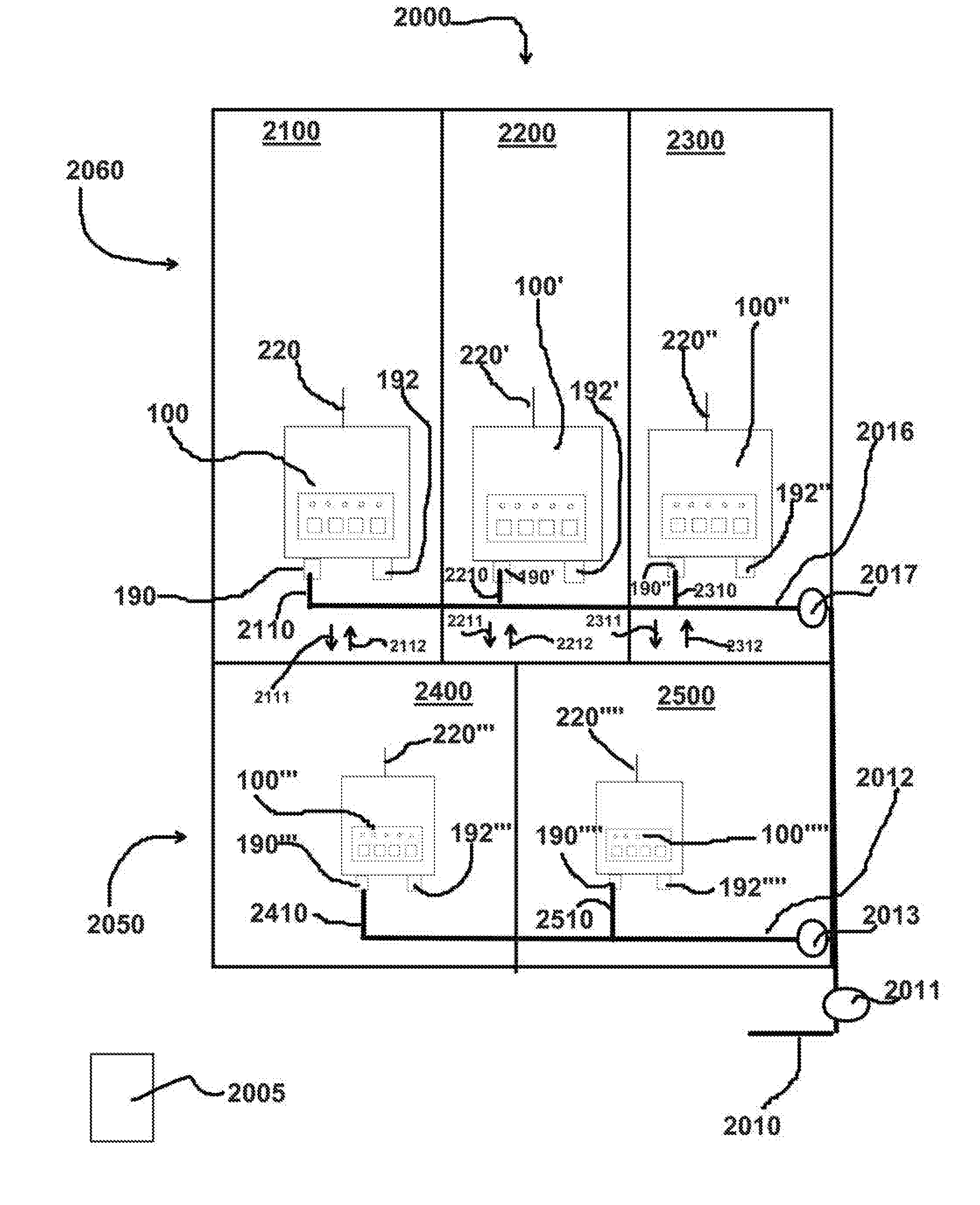
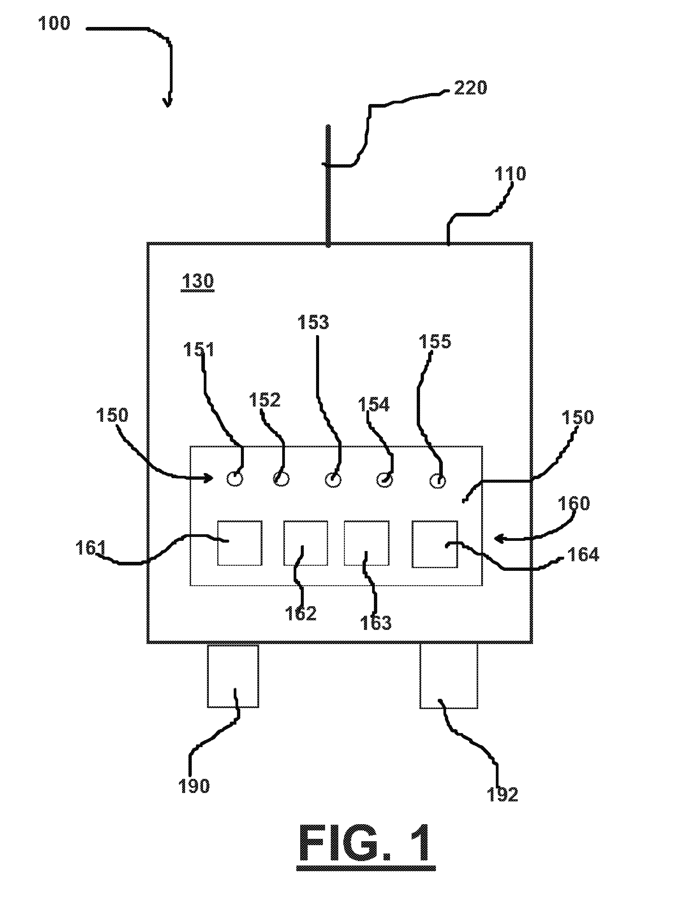
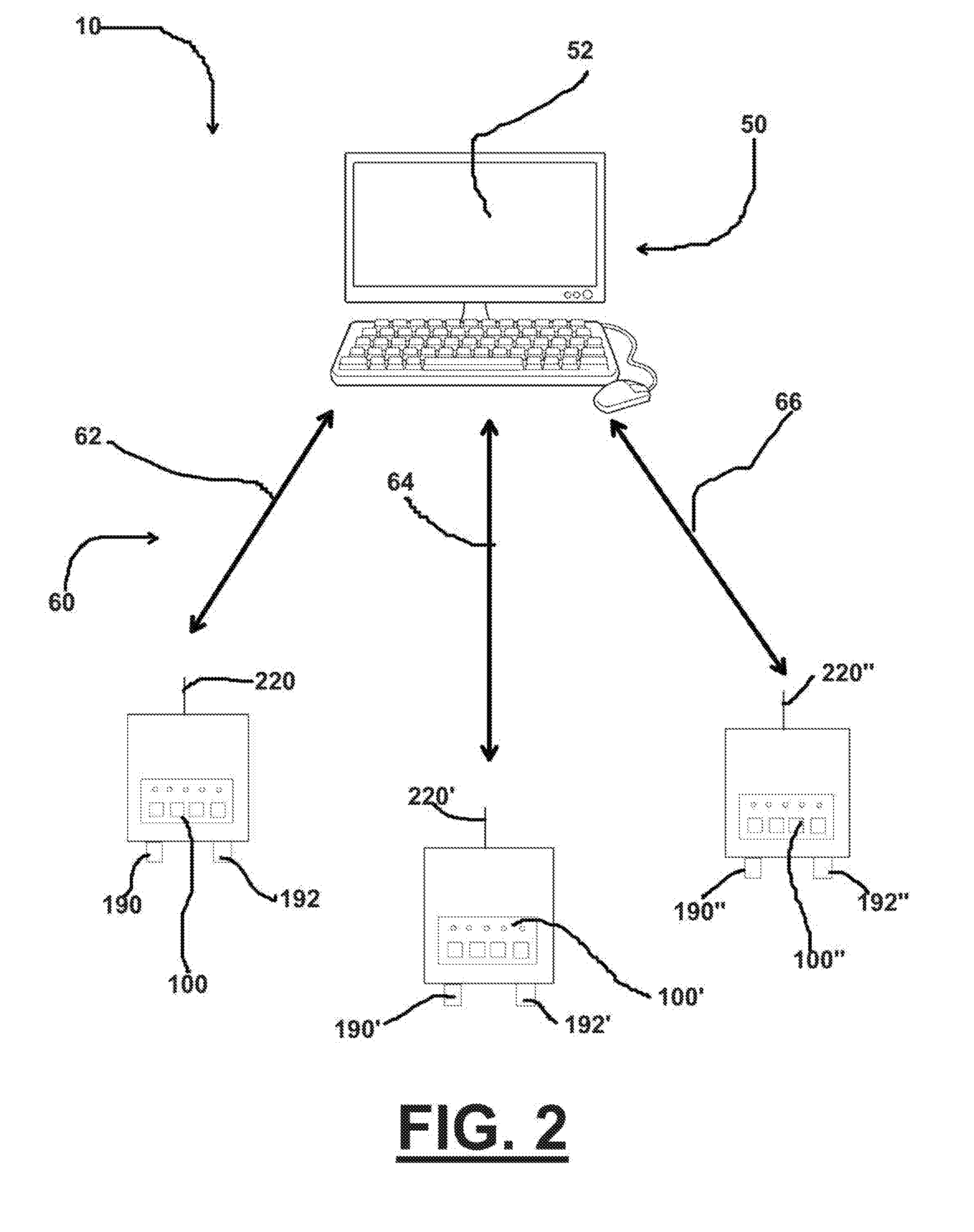
[0131]FIGS. 1 through 3 schematically diagram of one embodiment of the method and apparatus 10 which can include a central control 50 operatively connected to a plurality of metering units 100, 100′, 100″, etc. which plurality of metering units are themselves respectively operatively connected to a plurality of units 2100, 2200, 2300, 2400, and 2500 of a complex 2000.

[0132]FIG. 2 schematically illustrates components of the method and apparatus 10 comprising: (a) central control 50 ...


PUM


Abstract

A system and method for detecting multiple incidents in a set of flow meter units attached to a set of water consuming units. A plurality of uniquely identified flow meter units are operatively connected to a central control unit. The control unit is programmable to send alerts based on leaking incident status of particular flow meter units so that a responder may receive the alert and timely address the alert. The central control receives and stores data from the multiple flow meter units, including volumetric flow, time, and status and location of each alert. A method of detecting leaking in a building having multiple separate units, each unit having a unit water supply, includes placing a specially configured controller having a flow meter and automatic shut-off valve in each unit of the building. Leak sensors are positioned in water-leak risk areas wherein the controller communicates with both the flow meter and the sensors. A communication is established in between the controller and the sensors. One or more individuals are identified to receive an alert when leakage (or over-pressure conditions) occurs. Water flow is measured with the controller in multiple of the units and using one or more of the sensors. The measurements detect changes when compared to earlier established baseline parameters. An alert is sent to one or more of the individuals (e.g. owner(s), maintenance staff, management) when an abnormal water flow valve is measured.

Description

CROSS-REFERENCE TO RELATED APPLICATIONS[0001]This application claims benefit of U.S. Provisional Patent Application No. 62 / 198,508, filed 29 Jul. 2015. Incorporated herein by reference is United States Provisional Patent Application No. 62 / 198,508, filed 29 Jul. 2015, priority of which is hereby claimed.STATEMENT REGARDING FEDERALLY SPONSORED RESEARCH OR DEVELOPMENT[0002]Not applicableBACKGROUND[0003]Buildings such as high rise condominiums require careful control of leakage of the building fresh water supply system. In such buildings, even small leaks can grow into large problems because the unit may be unoccupied for long periods of time while the small leak is occurring, such as where the occupant of the leaking unit may be away on vacation for weeks or months at a time. A case of such water leakage if undetected can thus damage the structure of the building.[0004]There are a variety of leak detection systems with an automatic water shut off. Two sellers of leak protection equipm...

Claims


Application Information

Patent Timeline
IPC IPC(8): F17D5/06G08B21/20G08B5/22G01M3/26G01M3/28
CPCF17D5/06G01M3/26G08B21/20G08B5/223G01M3/2807Y02A20/15
Inventor DIETZEN, GARY H.MURPHY, RONALD R.BEASLEY, TERRY L.DIETZEN, DANIEL L.
Owner ENCO ELECTRONICS SYST LLC
Learn More