
Systems and Methods for Implementing Magnetoelectric Junctions Including Integrated Magnetization Components

a technology of integrated magnetization and magnetization junction, which is applied in the field of magnetoelectric junction implementation, can solve the problems of high power consumption, long wire cycle, and need to further reduce the switching current density, and achieve the effect of sufficient strength and facilitation of precessional switching of the free layer

Inactive Publication Date: 2017-02-02
INSTON
View PDF11 Cites 14 Cited by
  • Summary
  • Abstract
  • Description
  • Claims
  • Application Information

AI Technical Summary

Benefits of technology

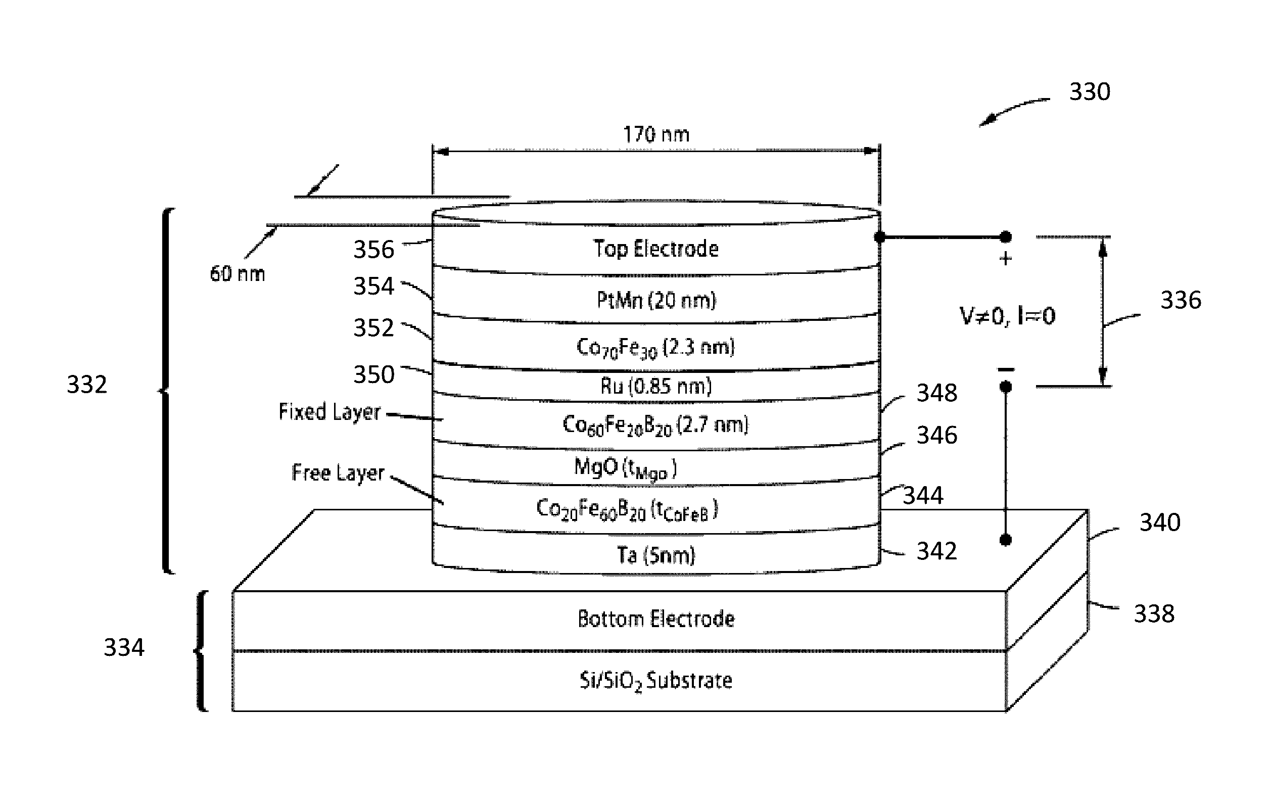
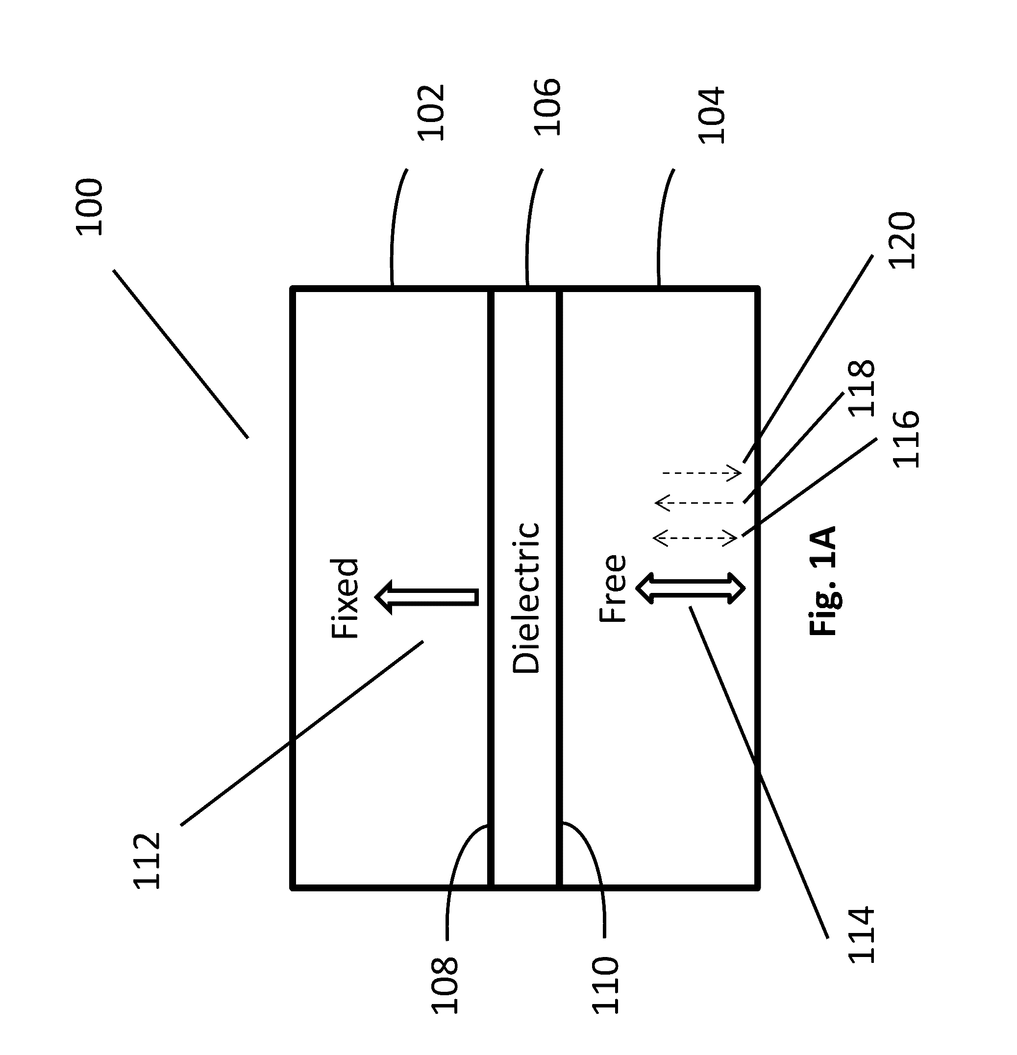
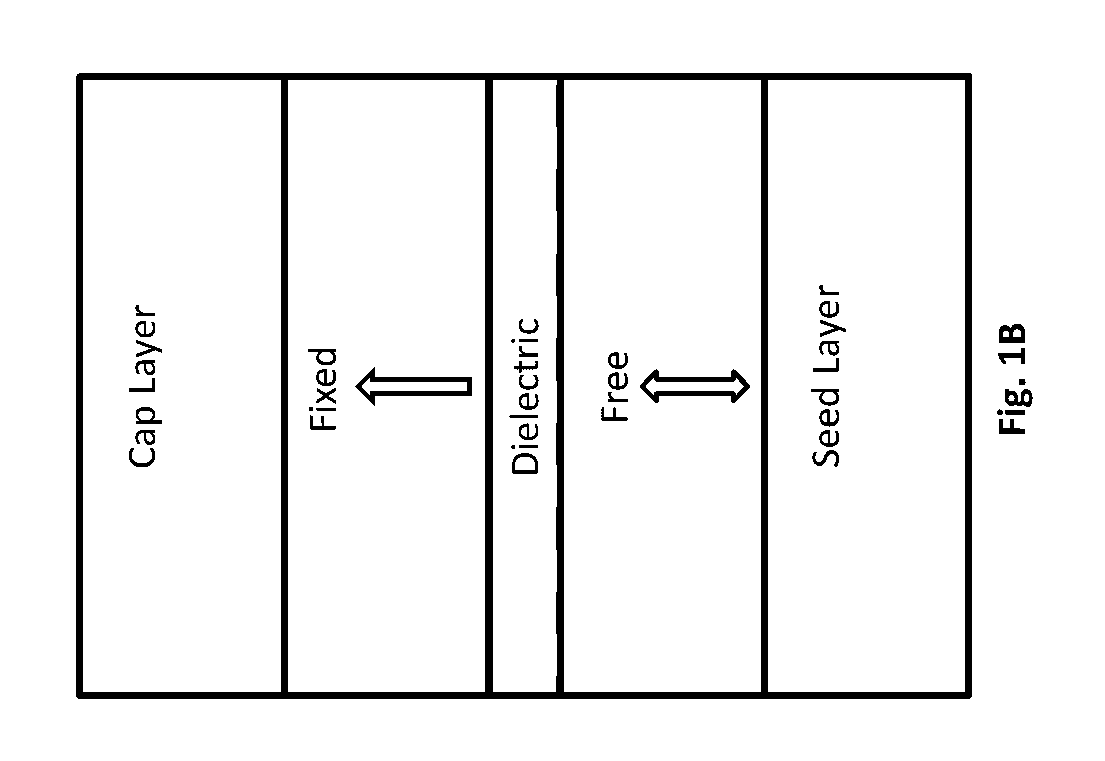
The invention relates to a magnetoelectric junction that includes a first ferromagnetic fixed layer, a ferromagnetic free layer, and a dielectric layer. The ferromagnetic free layer is magnetically anisotropic and can adopt a magnetization direction that is either parallel or antiparallel to the first direction. The junction also includes an antiferromagnetic layer that is adjacent to the ferromagnetic free layer. The magnetoelectric junction has a VCMA coefficient of at least 80 fJ / V·m and can switch its magnetization direction using a voltage pulse of the proper length. The technical effect of the invention is the creation of a magnetoelectric junction with integrated magnetization components that can switch its magnetization direction using a voltage pulse.

Problems solved by technology

MRAM technologies initially exhibited a number of technological challenges.
This technology also requires high power consumption and long wire cycles.
The challenge for STT-MRAM remains that the switching current density needs to be further reduced.

Method used


Image

  • Systems and Methods for Implementing Magnetoelectric Junctions Including Integrated Magnetization Components
  • Systems and Methods for Implementing Magnetoelectric Junctions Including Integrated Magnetization Components
  • Systems and Methods for Implementing Magnetoelectric Junctions Including Integrated Magnetization Components

Examples


Embodiment Construction

[0039]Turning now to the drawings, systems and methods for implementing magnetoelectric junctions including integrated magnetization components are illustrated. Previous efforts at implementing electromagnetic components that utilize magnetoresistance phenomena to achieve two information states (i.e. one bit of information), e.g. magnetic tunnel junctions (MTJs), were largely directed at using a current to manipulate the magnetization configuration (e.g. whether the magnetization directions of the fixed layer and the free layer are parallel or anti-parallel to each other) of the magnetic layers in the device. However, the currents required were often considerably large, particularly in cases where MTJs were used in MRAM configurations. Indeed, in applications that require low-power operation, the requirement of a considerably large current made the implementation of devices that rely on MTJs less commercially viable. Accordingly, voltage-controlled magnetic anisotropy-based MTJs (VM...


PUM


Abstract

Systems and methods in accordance with embodiments of the invention implement magnetoelectric junctions that include integrated magnetization components. In one embodiment, a magnetoelectric junction includes: a first fixed layer; a free layer; a dielectric layer disposed between the first fixed layer and the free layer; at least one magnetization layer that is disposed proximate the free layer; where: the first fixed layer is magnetized in a first direction; the free layer can adopt a magnetization direction that is either substantially parallel with or antiparallel with the first direction; the at least one magnetization layer is magnetized in a second direction that is orthogonal to the first direction; the magnetoelectric junction is characterized by a VCMA coefficient of at least approximately 80 fJ / V·m; and the magnetoelectric junction is configured such that a voltage pulse of a proper length in time can cause the free layer to invert its magnetization direction.

Description

CROSS-REFERENCE TO RELATED APPLICATIONS[0001]The current application claims priority to U.S. Provisional Application No. 62 / 198,589, filed Jul. 29, 2015, the disclosure of which is incorporated herein by reference.FIELD OF THE INVENTION[0002]The present invention generally relates to the implementation of magnetoelectric junctions.BACKGROUND OF THE INVENTION[0003]Devices that rely on electricity and magnetism underlie much of modern electronics. Researchers have recently begun to develop and implement devices that take advantage of both electricity and magnetism in spin-electronic (or so-called “spintronic”) devices. These devices utilize quantum-mechanical magnetoresistance effects, such as giant magnetoresistance (GMR) and tunnel magnetoresistance (TMR). GMR and TMR principles regard how the resistance of a thin film structure that includes alternating layers of ferromagnetic and non-magnetic layers depends upon whether the magnetizations of ferromagnetic layers are in a parallel ...

Claims


Application Information

Patent Timeline
IPC IPC(8): H01L43/08H01L43/10G11C11/16H01L43/02
CPCH01L43/08G11C11/161H01L43/10H01L43/02G11C11/1675H10N50/10H10N50/85H10N50/80
Inventor HU, QI
Owner INSTON
Learn More