
Nuclear magnetic resonance analysis method

a technology of nuclear magnetic resonance and analysis method, which is applied in the direction of nmr measurement, magnetic measurement, instruments, etc., can solve the problems of relatively long and tedious correction steps, phased array, and significantly increased complexity of electronics and computer processing of signals produced separately by each of the antennas, so as to achieve efficient and simple phase shift correction and phase shift efficient and simple

Active Publication Date: 2017-02-23
UNIV DE PROVENCE D AIX MARSEILLE I +1
View PDF5 Cites 6 Cited by
  • Summary
  • Abstract
  • Description
  • Claims
  • Application Information

AI Technical Summary

Benefits of technology

The invention provides a way to make a modified spectrum without noise, by substituting a portion of the spectrum from two different portions of the spectrum. This technique is useful for characterizing samples, such as by using coils to capture complex FID signals. The invention also helps to correct phase shift and frequency offset caused by sample movements and field inhomogeneity. Its technical benefits include improved accuracy and efficiency in analyzing samples.

Problems solved by technology

It should be noted here that the electrical signals which must be detected with these antennas are usually low or very low, and that the challenge is to distinguish these from the level of the intrinsic noise of the electrical equipment used.
Such correction steps are relatively long and tedious.
This type of antenna, called “phased array antenna”, is characterized by a significantly increased complexity of electronics and computer processing of the signals produced separately by each of the antennas in the array.

Method used


Image

  • Nuclear magnetic resonance analysis method
  • Nuclear magnetic resonance analysis method
  • Nuclear magnetic resonance analysis method

Examples


Embodiment Construction

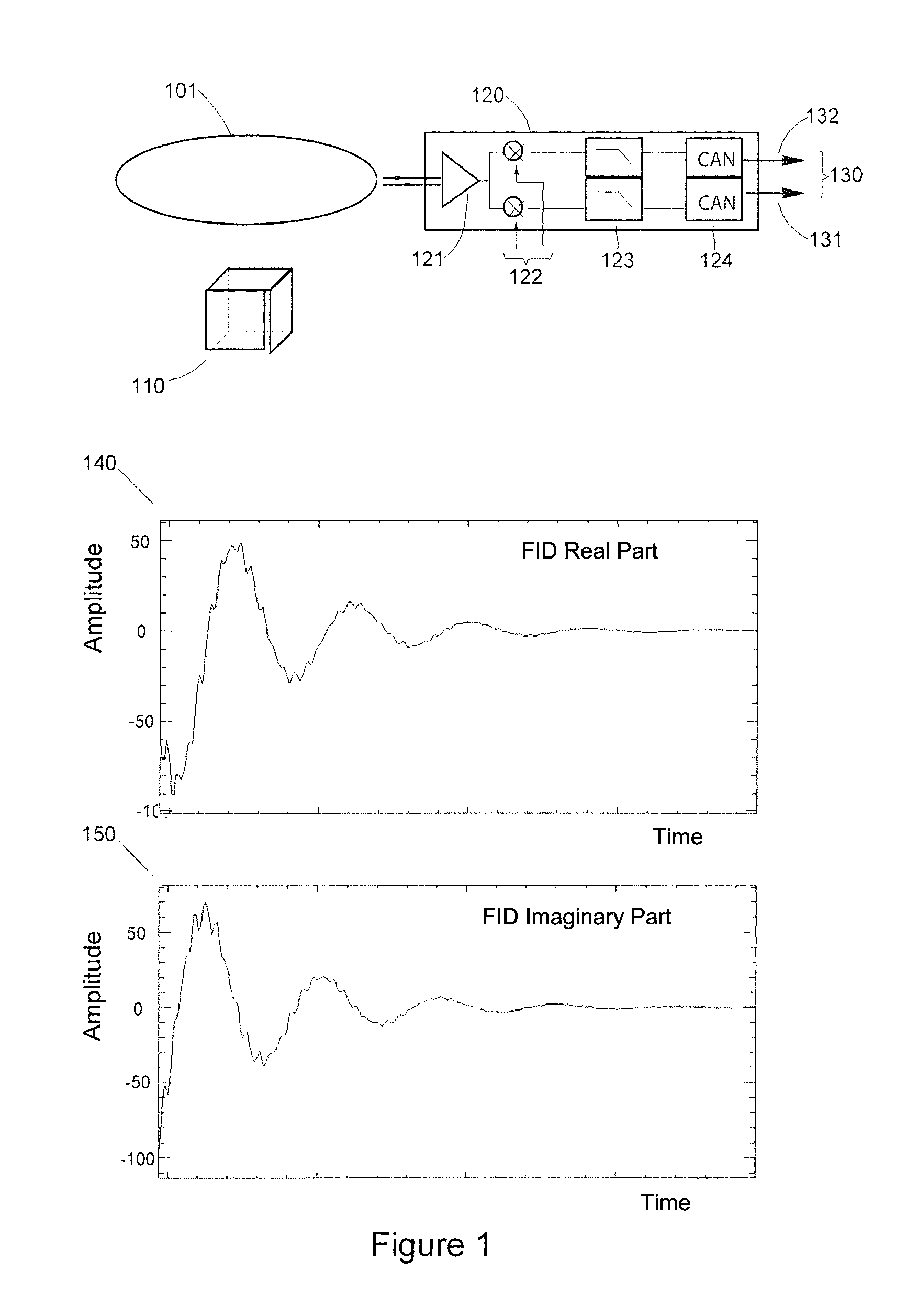
[0112]FIG. 1 briefly describes the type of signals detected by any antenna of NMR equipment. The signal may be observed after each emission of an electromagnetic pulse B1 used to disturb the hydrogen nuclei, or protons which are steady in the constant magnetic field B0. As seen above, the RF frequency used should preferably be resonating with the Larmor frequency of protons for the intensity of the magnetic field B0 developed by the NMR equipment considered and which is all the higher as the field B0 is great. As mentioned above, it grows by 42 MHz per Tesla. The detected NMR signal is called a FID (for “free induction decay”) signal. It is representative of the return to a steady-state of the nuclei after the electromagnetic disturbance which they are subject to has ceased. Using conventional means which are not described and which are not necessary for understanding the invention, the captured FID signal is delivered by an elementary volume unit of the area covered by the antenna ...


PUM


Abstract

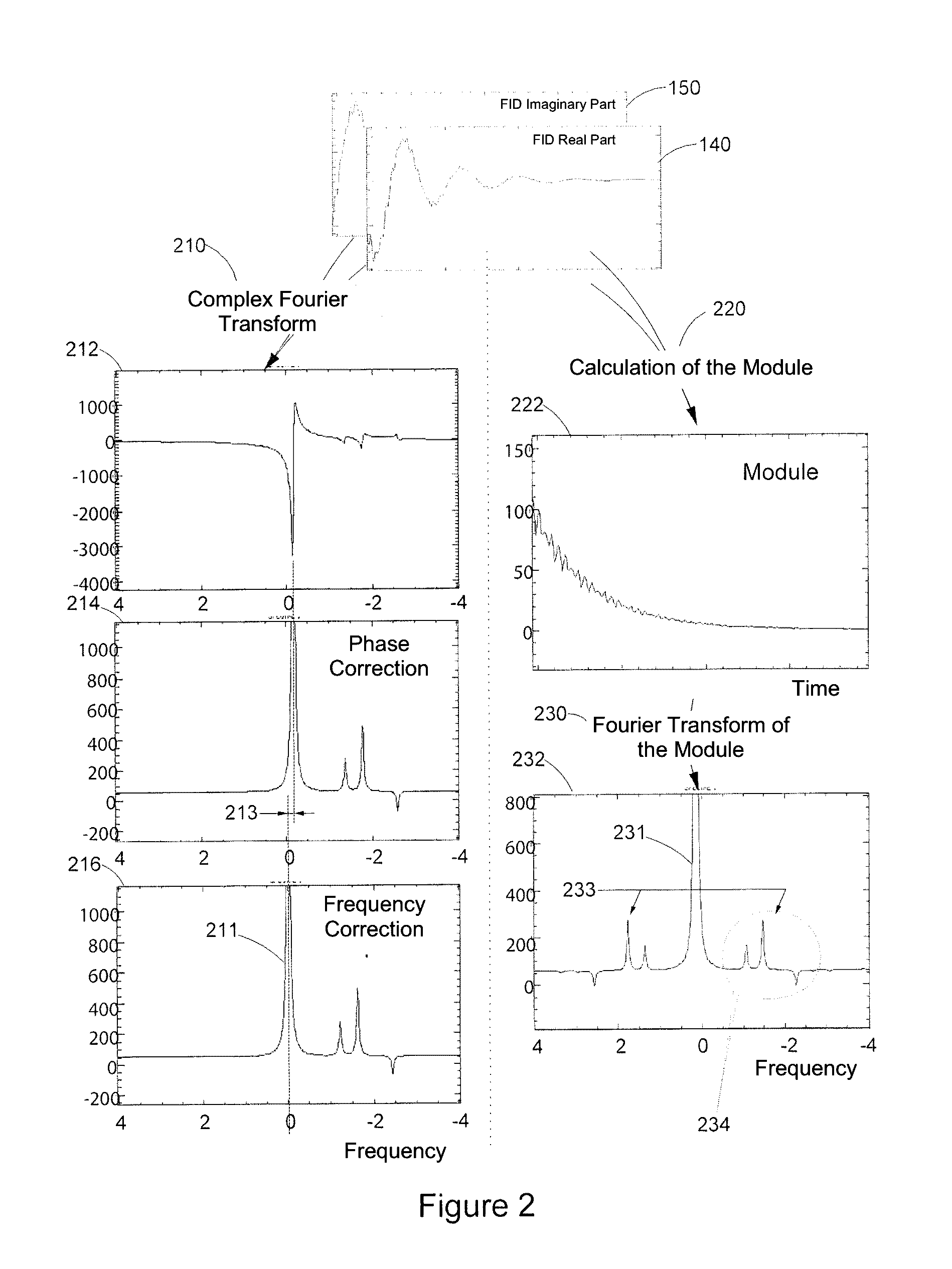
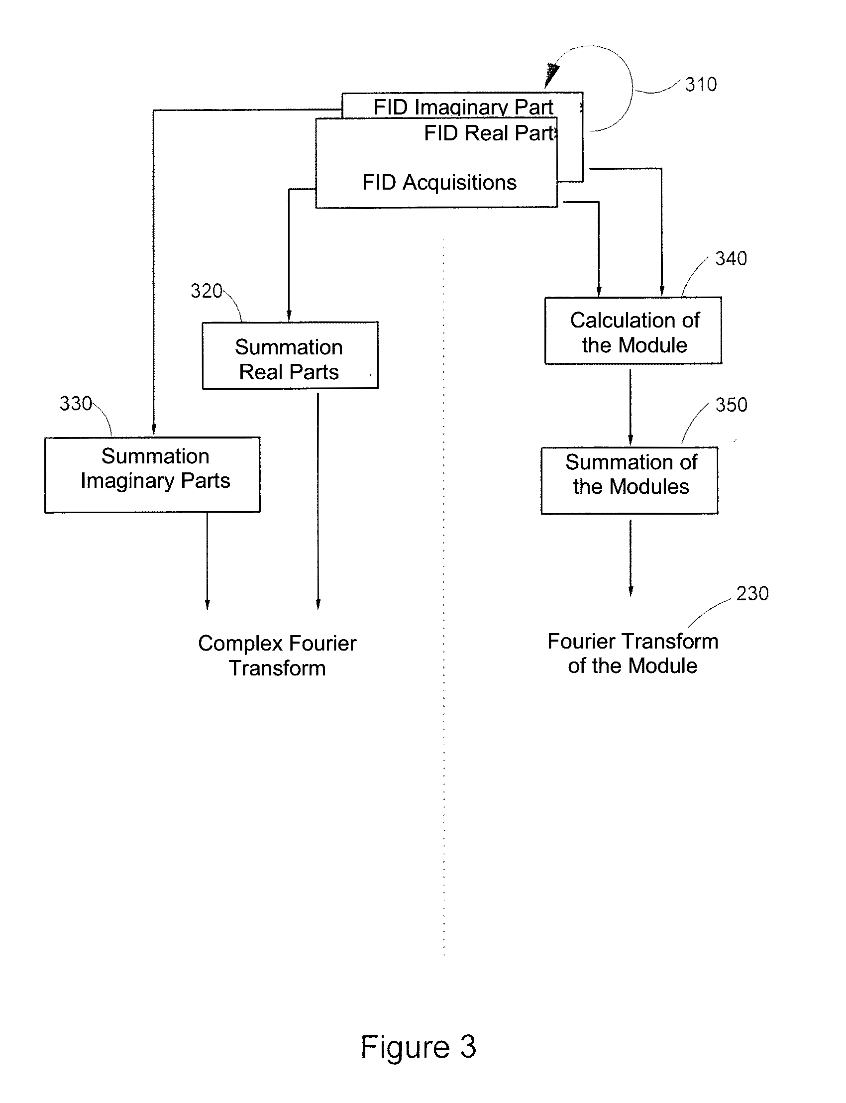
Method for analyzing a sample including a species to be characterized and a reference species, includes:acquiring one or more complex free induction decay (FID) signal(s) (S(t)),obtaining a FID spectrum S(ω) by applying a Fourier transform to the signal S(t), with the FID spectrum obtained including two portions, each extending from the resonance frequency of the reference species (F0ref) and respectively on either side of F0Ref, with the frequency of the species to be characterized located on a portion of the spectrum;modeling the signal of the reference species from the real and complex parts of the at least one complex FID signal;obtaining a spectrum Sref(ω) of the reference species including the reference species only,obtaining a modified FID {tilde over (S)}(ω) spectrum;applying a reverse Fourier transform to {tilde over (S)}(ω) to obtain a modified signal {tilde over (s)}(t);calculating the module of the {tilde over (s)}(t) modified FID signal.

Description

TECHNICAL FIELD OF THE INVENTION[0001]The present invention generally relates to nuclear magnetic resonance (NMR) techniques used in particular for analyzing samples. The present invention advantageously applies to the field of medicine for analyzing biological samples from human bodies for example or to the field of chemistry for analyzing chemical compositions. It is particularly advantageous for correcting the phase and / or the frequency of a free induction decay (FID) signal. In one advantageous but non-limiting application, the invention will be used for effectively recombining the NMR signals detected by antenna arrays.STATE OF THE ART[0002]Nuclear magnetic resonance (NMR) was discovered in the forties, and has become increasingly important in many areas of science for analyzing materials and more particularly in medicine for the in vivo observation of the human body. Numerous applications of this discovery have been implemented. In the medical field, magnetic resonance imaging...

Claims


Application Information

Patent Timeline
Patent Type & Authority Applications(United States)
IPC IPC(8): G01R33/46G01R33/465
CPCG01R33/465G01R33/4625
Inventor LE FUR, YANN
Owner UNIV DE PROVENCE D AIX MARSEILLE I
Learn More