Non-pneumatic tire

a non-pneumatic tire technology, applied in the direction of tyre parts, tyre tread bands/patterns, transportation and packaging, etc., can solve the problems of deterioration in durability of non-pneumatic tires, and large hysteresis loss in the tread portion, etc., to suppress the degradation of the tread portion and improve durability. , the effect of large thermal conductivity

Active Publication Date: 2017-03-02
SUMITOMO RUBBER IND LTD
View PDF9 Cites 12 Cited by
  • Summary
  • Abstract
  • Description
  • Claims
  • Application Information

AI Technical Summary

Benefits of technology

[0012]The present invention provides a non-pneumatic tire including an annular tread portion for coming into contact with a road surface, an annular inner portion disposed inward of the tread portion in a tire radial direction and a plurality of connecting portions connecting the tread portion and the inner portion. The tread portion includes a first portion that comes into contact with the road surface and a second portion comprising an inner surface facing the inner portion, and a thermal conductivity of the second portion is greater than a thermal conductivity of the first portion. When grounding, the first portion is heated due to repeated compressive and tensile deformation of the tread portion. The heat of the first portion is dissipated smoothly to the outside through the inner surface of the second portion which has a large thermal conductivity. Accordingly, the non-pneumatic tire according to the present invention suppresses degradation of the tread portion due to heat and exhibits an excellent durability.

Problems solved by technology

In such a non-pneumatic tire, when traveling, a large hysteresis loss occurs in the tread portion by being repeated compressive and tensile deformation of the tread portion.
Hysteresis loss generates heat energy that heats the tread portion.
The heat tends to degrade the tread portion and will cause deterioration in durability of the non-pneumatic tire.

Method used


Image

  • Non-pneumatic tire
  • Non-pneumatic tire
  • Non-pneumatic tire

Examples


example

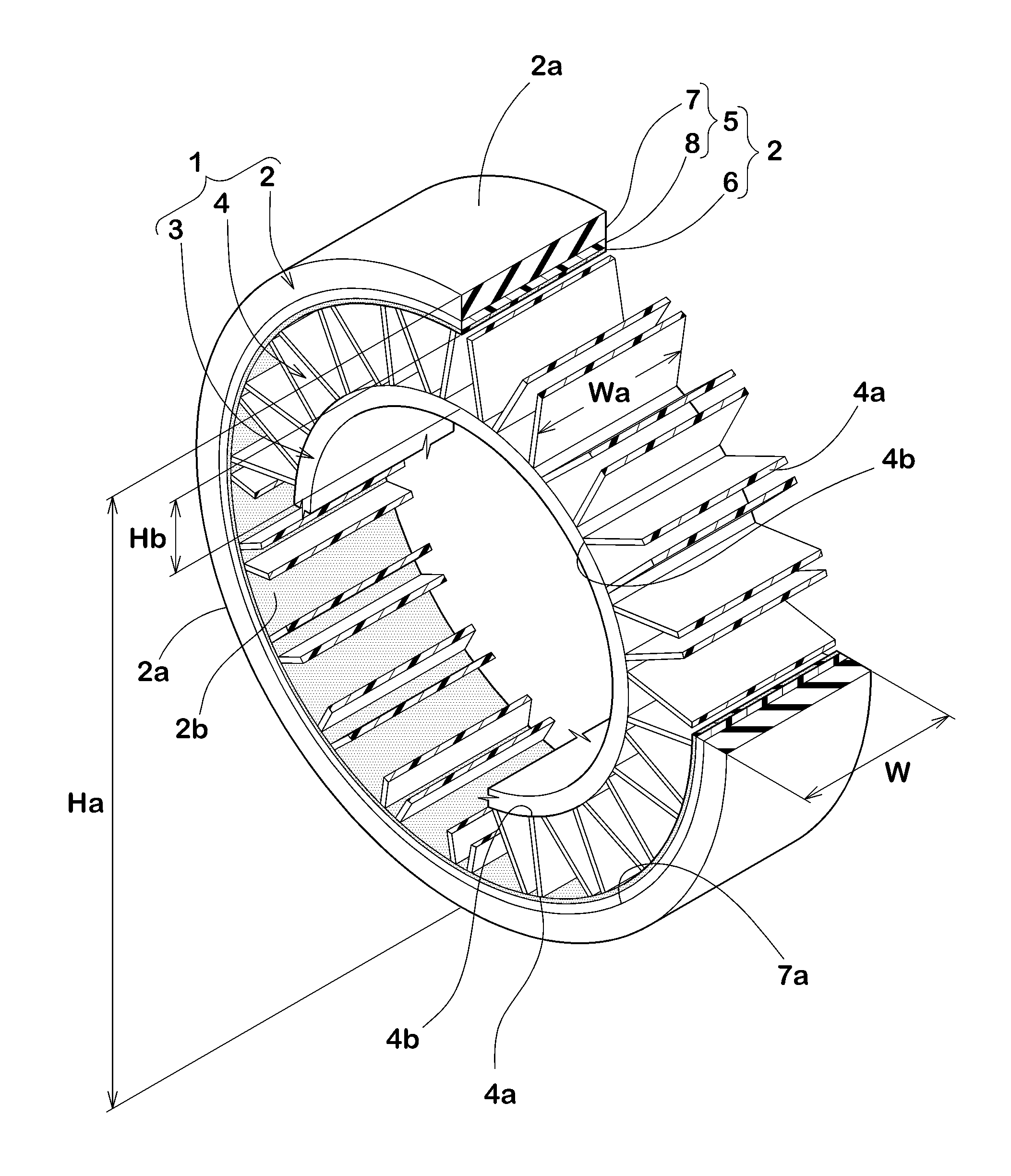
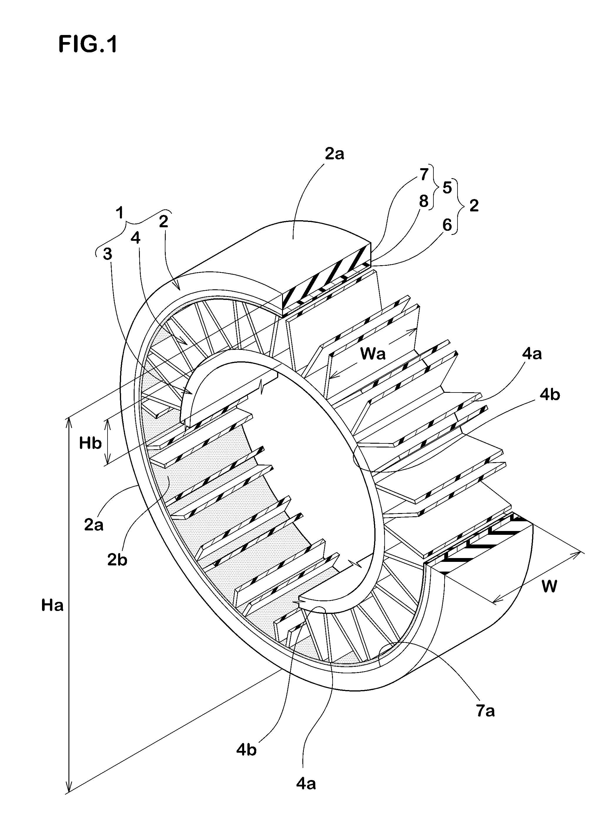
[0041]Non-pneumatic tires having a basic structure illustrated in FIG. 1 were manufactured based on the specifications of Table 1, and then heat-generating property and crack-damage resistance of the tires were tested. Common specifications of the tires and test procedures are as follows.

[0042]Tire outer diameter Ha: 635 mm

[0043]Tread portion width W: 195 mm

[0044]Material of outer layer of first portion: natural rubber and styrene-butadiene rubber

[0045]Material of inner layer of first portion: thermosetting polyurethane resin (thermal conductivity: 0.25 W / (m·K))

[0046]Thermal conductivity k1 of first portion: 0.21 W / (m·K)

[0047]Material of second portion: silicone based rubber (thermal conductivity k2: 1.9 W / (m·K))

[0048]Material of second portion: urethane based rubber (thermal conductivity k2: 0.8 W / (m·K))

[0049]Material of inner portion: thermosetting polyurethane resin

[0050]Radial heights of connecting portions Hb: 90 mm

[0051]Widths of connecting portions Wa: 185 mm

[0052]Material of...


PUM

PropertyMeasurementUnit
thicknessaaaaaaaaaa
surface roughnessaaaaaaaaaa
thermal conductivityaaaaaaaaaa

Abstract

Provided is a non-pneumatic tire having excellent durability performance. This non-pneumatic tire is provided with an annular tread portion which contacts the road surface, an annular inner peripheral portion which is positioned radially inward of the tread portion, and multiple linking units which join the tread portion and the inner peripheral portion. The tread portion includes a first portion which contacts the road surface, and a second portion which includes an inner peripheral surface facing the inner peripheral portion. The thermal conductivity of the second portion is greater than that of the first portion.

Description

TECHNICAL FIELD[0001]The present invention relates to a non-pneumatic tire having an excellent durability.BACKGROUND ART[0002]Non-pneumatic tires which comprise an annular tread portion for coming into contact with a road surface, an annular inner portion disposed inward of the tread portion in a tire radial direction and a plurality of connecting portions connecting the tread portion and the inner portion have been known. The tread portion generally includes a portion formed of rubber or resin. In such a non-pneumatic tire, when traveling, a large hysteresis loss occurs in the tread portion by being repeated compressive and tensile deformation of the tread portion. Hysteresis loss generates heat energy that heats the tread portion. The heat tends to degrade the tread portion and will cause deterioration in durability of the non-pneumatic tire.CITATION LISTPatent LiteraturePatent Literature 1: Japanese Unexamined Patent Application Publication No. 2008-132951Patent Literature 2: Jap...

Claims


Application Information

Patent Timeline
Patent Type & Authority Applications(United States)
IPC IPC(8): B60C7/14B60B9/26B60B9/04
CPCB60C7/14B60B9/04B60B9/26B60B2360/32B60B2360/50B60B2360/324B60C2007/146B60C7/00B60C7/102B60C7/143B60C11/005B60C7/107B60C7/146
Inventor SUGIYA, MAKOTOIWAMURA, WAKO
Owner SUMITOMO RUBBER IND LTD
Why Eureka
Try Eureka