Piezoelectric element and piezoelectric element applied device

a piezoelectric element and piezoelectric technology, applied in the direction of device details, device material selection, piezoelectric/electrostrictive device details, etc., can solve the problems of piezoelectric characteristics, piezoelectric characteristics are easily generated, and the realization of improving piezoelectric characteristics is not possible. achieve the effect of improving piezoelectric characteristics

Active Publication Date: 2017-03-02
SEIKO EPSON CORP
View PDF1 Cites 5 Cited by
  • Summary
  • Abstract
  • Description
  • Claims
  • Application Information

AI Technical Summary

Benefits of technology

[0014]In the aspect, it is possible to provide a piezoelectric element applied device in which at least on...

Problems solved by technology

If the KNN thin film is formed by using the solution method in which high productivity is possible, there is a problem in that a void is easily generated, and the void influences the piezoelectric characteristics and the occurrence of a leakage current.
Because the piezoelectric characteristics may be deteriorated by suppressing the occurrence of the void, realization of impr...

Method used


Image

  • Piezoelectric element and piezoelectric element applied device
  • Piezoelectric element and piezoelectric element applied device
  • Piezoelectric element and piezoelectric element applied device

Examples


embodiment 1

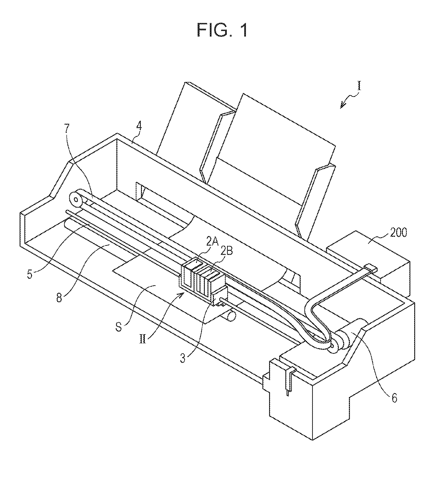
[0030]FIG. 1 illustrates an ink jet type recording apparatus which is an example of a liquid ejecting apparatus according to an embodiment of the invention. As illustrated in FIG. 1, in an ink jet type recording apparatus I, an ink jet recording head unit (head unit) II which includes a plurality of ink jet recording heads is provided so as to be attachable to cartridges 2A and 2B. The cartridges 2A and 2B constitute an ink supply section. A carriage 3 having the head unit II mounted therein is provided with a carriage shaft 5 so as to be movable in a shaft direction. The carriage shaft 5 is attached to a main body 4 of the apparatus. For example, the carriage 3 has a function of discharging a black ink composition and a color ink composition.

[0031]A driving force of a driving motor 6 is transferred to the carriage 3 through a plurality of gears and timing belts 7 (not illustrate). Thus, the carriage 3 having the head unit II mounted therein is moved along the carriage shaft 5. A tr...

examples

[0073]Examples of the invention will be described below.

examples 1 to 3

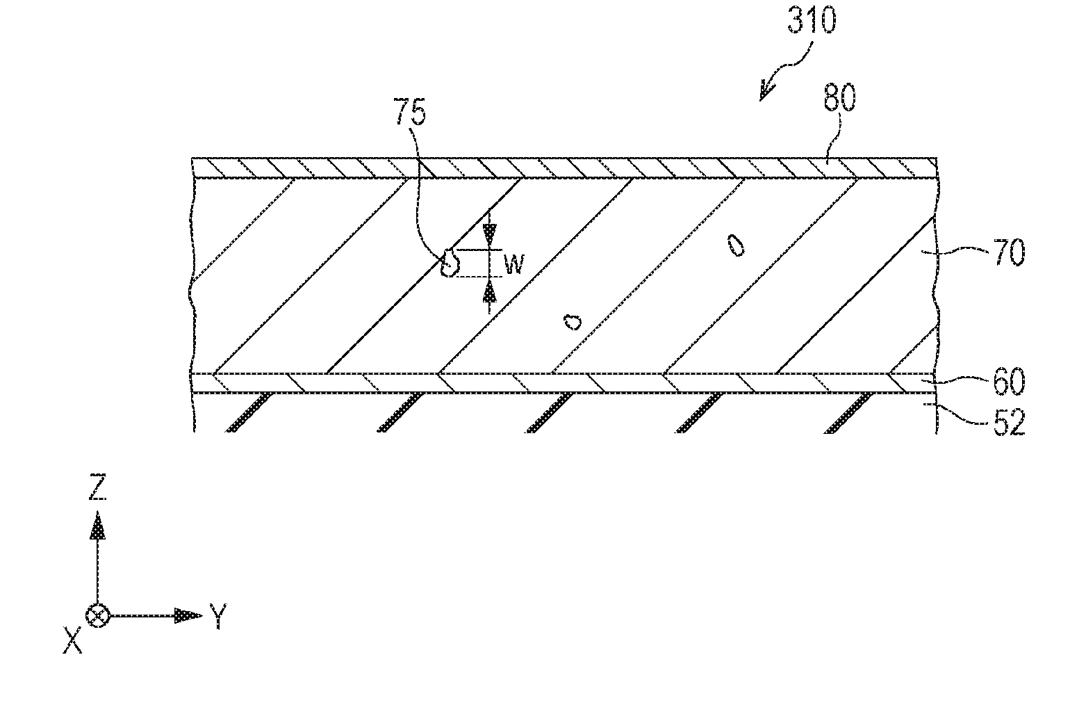
[0074]A surface of a silicon substrate which is used as the substrate 10 was thermally oxidized, and thus the elastic film 51 formed from silicon dioxide was formed on the silicon substrate. Then, a zirconium film was formed on the elastic film 51 by sputtering, and the zirconium film was thermally oxidized. Thus, the insulating film 52 formed from zirconium oxide was formed. Then, a titanium film was formed on the insulating film 52 by sputtering, thereby forming the adhesive layer 56. After a platinum film was formed on the adhesive layer 56 by using a sputtering method, the platinum film was patterned so as to have a predetermined shape. Thus, the first electrode 60 having a thickness of 50 nm was formed.

[0075]Then, the piezoelectric layer 70 was formed through the following procedures. Firstly, an n-octane solution of potassium acetate, an n-octane solution of sodium acetate, and an n-octane solution of pentaethoxy niobium were mixed, thereby preparing a precursor solution. Thre...


PUM


Abstract

There is provided a piezoelectric element which includes a first electrode, a piezoelectric layer which is formed on the first electrode by using a solution method, and is formed from a compound oxide having a perovskite structure in which potassium, sodium, and niobium are provided, and a second electrode which is provided on the piezoelectric layer. A cross-sectional SEM image of the piezoelectric layer is captured at a magnification of 100,000. When evaluation is performed under a condition in which a measured value in a transverse direction is set to 1,273 nm, two or more voids are included in the piezoelectric layer, a difference between the maximum value and the minimum value among diameters of the voids to be largest in a film thickness direction is equal to or smaller than 14 nm, and the maximum value is equal to or smaller than 24 nm.

Description

BACKGROUND[0001]1. Technical Field[0002]The present invention relates to a piezoelectric element which includes a first electrode, a piezoelectric layer, and a second electrode, and a piezoelectric element applied device which includes the piezoelectric element.[0003]2. Related Art[0004]Generally, a piezoelectric element includes a piezoelectric layer and two electrodes. The piezoelectric layer has electromechanical conversion characteristics. The piezoelectric layer is interposed between the two electrodes. A device (piezoelectric element applied device) which uses such a piezoelectric element as a driving source has been recently actively developed. As one of the piezoelectric element applied device, for example, a liquid ejecting head represented by an ink jet recording head, a MEMS element represented by a piezoelectric MEMS element, an ultrasonic measurement device represented by an ultrasonic sensor and the like, and a piezoelectric actuator device are provided.[0005]As one of...

Claims


Application Information

Patent Timeline
IPC IPC(8): H01L41/04H01L41/18H01L41/08
CPCH01L41/04B41J2/14201H01L41/18H01L41/0805B41J2/0452H10N30/1051H10N30/85H10N30/8542B41J2/14233B41J2002/14241B41J2202/03H10N30/078H10N30/80
Inventor SAKAI, TOMOHIROSUMI, KOJIISSHIKI, TETSUYATAKAHASHI, TOSHIAKIKOBAYASHI, TOMOKAZUKITADA, KAZUYA
Owner SEIKO EPSON CORP
Why Eureka
Try Eureka