Beam steerable communication apparatus

Active Publication Date: 2017-03-02
OBSHCHESTVO S OGRANICHENNOJ OTVETSTVENNOSTYU RADIO GIGABIT
View PDF1 Cites 30 Cited by
  • Summary
  • Abstract
  • Description
  • Claims
  • Application Information

AI Technical Summary

Benefits of technology

[0031]According to one embodiment, phase shifting is performed in RF region with signals on a carrier frequency. RF phase shifting has the advantage of higher dynamic range of the transceiver, but involves additional loss since the realization of a phase shifter in millimeter wave range is quite complicated.
[0032]According to another embodiment,

Problems solved by technology

The requirement for high gain value is determined by a small wavelength of radiation in millimeter wave frequency range, which leads to difficulties in transmitting a signal over long distances using antennas with insufficient gain values.
This absorption can be compensated only by using high gain antenna systems since the emitted power level is generally limited by the regulation requirements and transceiver performance.
However, the use of antennas with a narrow radiation pattern beam involves difficulties related to antenna alignment and probability of connection refuse in case of even small orientation changes of the anten

Method used


Image

  • Beam steerable communication apparatus
  • Beam steerable communication apparatus
  • Beam steerable communication apparatus

Examples


Embodiment Construction

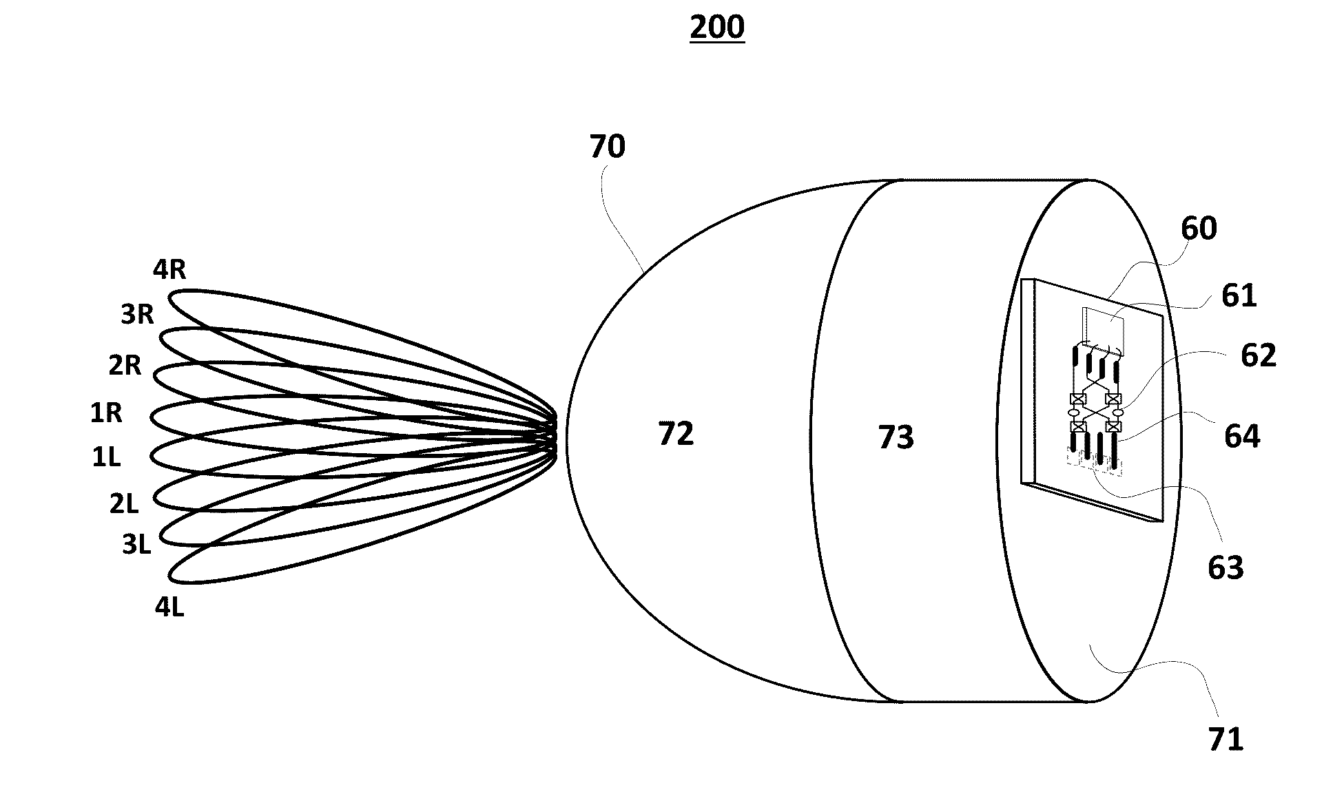
[0043]According to the invention, it is provided a high data rate communication apparatus with an antenna with high gain value and effective beam-scanning capability providing low loss and the capability to combine signal powers from different transceiver outputs without RF linearity degradation.

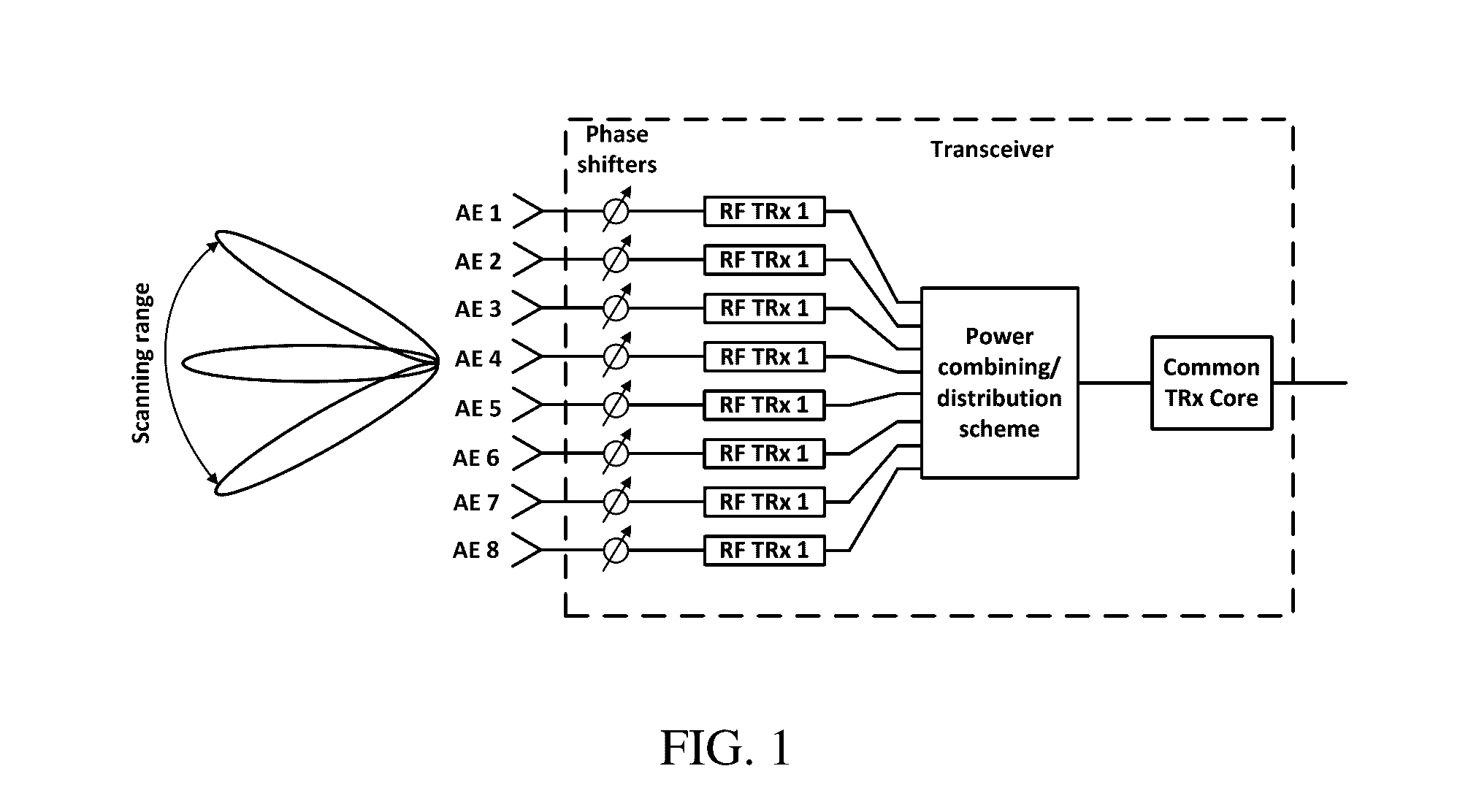
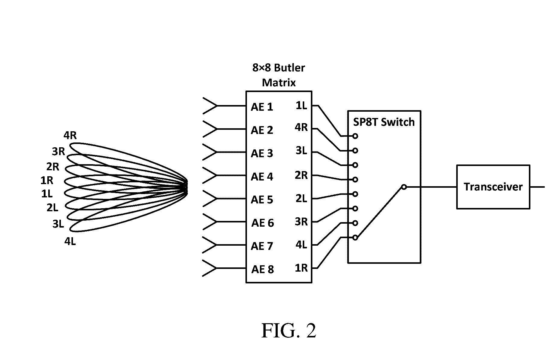
[0044]An example of a communication apparatus 100 according to the invention is presented in FIG. 4. The apparatus comprises a dielectric lens 10, a plurality of antenna elements 20-1 . . . 20-N which are primary antenna elements for a lens 10, a bemforming network 30 represented by a Butler matrix, and a transceiver block 40 with a plurality of outputs on which signal phases can be adjusted and controlled. Not shown (for clarity reasons) also a baseband modem which performs control of phase values of signals at each output of the transceiver block 40 through a control channels between the baseband modem and the transceiver block 40. In this example phase shifters 41-1 . . . 41-N operate wit...


PUM


Abstract

Disclosed is a beam steerable communication apparatus comprising a focusing element with a focal plane, a plurality of antenna elements disposed on the focal plane of the focusing element, a beamforming network which has a plurality of antenna ports and a plurality of beamforming ports, at least one radio frequency transceiver capable to control the phase of carrier frequency signals on its independent outputs, and a baseband modem, wherein each antenna port of the beamforming network is coupled to at least one antenna element, each beamforming port of the beamforming network is coupled to an independent transceiver output, and the phase distribution law formed on the beamforming ports is determined by a baseband modem control commands to the transceivers, said phase distribution law is to combine or distribute signal power on all beamforming ports from or to at least one antenna port of the beamforming network, wherein each radio frequency transceiver includes at least a phase shifter, a Tx/Rx switch, LNA, PA, up and down-conversion mixers, LO generation circuit, receive power combining and transmit power distribution schemes. The technical result of the invention is in the capability of providing efficient beam steering with high gain antennas with all the prospect features of phased antenna arrays, such as the ability to combine/distribute signal power between several RF amplifiers, thus, facilitating linearity requirements and increasing an output power of a transmitter. The present invention can be used, without limitations, in radio relay point-to-point communication systems, e.g. for forming backhaul networks of cellular mobile communication, in car radars and other radars, in local and personal communication systems, in satellite and intersatellite communication systems, etc.

Description

CROSS-REFERENCE[0001]The present application claims convention priority to Russian Utility Patent Application No. 2014117983, filed on May 6, 2014, entitled “BEAM STEERABLE COMMUNICATION APPARATUS”. This application is incorporated by reference herein in its entirety. The present application is a continuation of International Patent Application no. PCT / RU2015 / 000278, filed on Apr. 29, 2015, entitled “BEAM STEERABLE COMMUNICATION APPARATUS”. This application is incorporated by reference herein in its entirety.FIELD OF THE INVENTION[0002]The present invention relates to the field of communication systems, more particularly, to novel high data rate communication apparatus with an antenna system capable to electronic beam steering. The disclosed apparatus can be effectively used in various applications of millimeter wave radio communication systems, such as radio relay point-to-point communication systems and backhaul networks of mobile cellular communications, radars, satellite and int...

Claims


Application Information

Patent Timeline
IPC IPC(8): H01Q19/08H01Q3/40H01Q1/22H01Q9/06H04B7/06H01Q1/38
CPCH01Q19/08H04B7/0617H01Q3/40H01Q1/2283H01Q9/065H01Q1/38H01Q3/245H01Q25/007
Inventor ARTEMENKO, ALEKSEY ANDREEVICHMASLENNIKOV, ROMAN OLEGOVICH
Owner OBSHCHESTVO S OGRANICHENNOJ OTVETSTVENNOSTYU RADIO GIGABIT
Why Eureka
Try Eureka